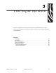
3 Print Engine Operation If you have completed the tasks and resolved issues in the checklist in Before You Begin on page 14, use this chapter to load the print engine, to calibrate the print engine, and to print configuration labels. Contents Load Media . . . . . . . . . . . . . . . . . . . . . . . . . . . . . . . . . . . . . . . . . . . . . . . . . . . . . . . . . . . Load Ribbon. . . . . . . . . . . . . . . . . . . . . . . . . . . . . . . . . . . . . . . . . . . . . . . . . . . . . . . . . . .
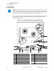
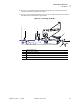
Print Engine Operation Load Media Load Media Important • If the print engine power is Off (O), rollers in the print engine can turn if you pull on the media. This could cause loaded ribbon to become slack and possibly wrap around the auxiliary roller. If you load or unload media with the power off, inspect the auxiliary roller to make sure that no ribbon is wrapped around it before turning On (I) the power. Figure 18 identifies the media-handling components of a right-hand print engine.
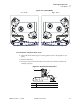
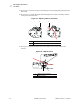
Print Engine Operation Load Media Figure 19 • Loaded Media Left-Hand Right-Hand To load media, complete these steps: 1. Load media on the media supply reel of the applicator (refer to the applicator’s user guide). 2. Open the media door. 3. See Figure 20. Press the release button on the pinch roller assembly, and allow the assembly to pivot up. Figure 20 • Opening the Pinch Roller 1 2 1 2 58981L-002 Rev.
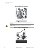
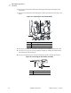
Print Engine Operation Load Media 4. See Figure 21. Slide the outer media guide all the way out. Figure 21 • Sliding the Outer Media Guide 1 1 Outer media guide 5. See Figure 22. Open the printhead assembly by unlatching the printhead latch from the locking pin. Caution • The printhead may be hot and could cause severe burns. Allow the printhead to cool. Figure 22 • Opening the Printhead Assembly 1 2 1 2 34 Printhead latch Locking pin R110PAX4 User Guide 58981L-002 Rev.
Print Engine Operation Load Media 6. See Figure 23. Thread the media under the upper guide post, below the pinch roller assembly, and under the printhead assembly. 7. See Figure 23. Extend approximately 30 in. (75 cm) of media past the peel bar. Remove and discard the labels from this exposed media. Figure 23 • Threading the Media 1 2 3 4 5 1 2 3 4 5 58981L-002 Rev.
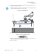
Print Engine Operation Load Media 8. See Figure 24. Position the media so that it is aligned with and just touching the inner media guide. 9. See Figure 24. Position the outer media guide so that it just touches the outer edge of the media. Figure 24 • Adjusting the Outer Media Guide 1 2 3 1 2 3 Inner media guide Outer media guide Media 10. See Figure 20 on page 33. Press down on the pinch roller assembly until it locks closed. 11. See Figure 22 on page 34.
Print Engine Operation Load Media 13. See Figure 26. Thread the media liner around the peel bar, under the media liner roller, and through the peel roller assembly. Note • If the applicator has an air tube, route the media liner between the air tube and the peel bar. Do not thread the media liner over the air tube. Figure 26 • Threading the Liner 1 1 2 3 4 2 3 4 Lower guide post Peel bar Media liner roller Peel roller assembly 14. See Figure 27.
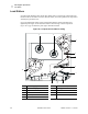
Print Engine Operation Load Ribbon Load Ribbon Use ribbon with thermal transfer media. The ribbon must be coated on the outside and wider than the media. If the ribbon is narrower than the media, areas of the printhead are unprotected and subject to premature wear. Figure 28 identifies the ribbon system components inside the media compartment of a right-hand print engine. A left-hand unit contains a mirror image of these components. Figure 29 on page 39 shows the print engine with ribbon loaded.
Print Engine Operation Load Ribbon Figure 29 • Loaded Ribbon Left-Hand Right-Hand To load ribbon, complete these steps: 1. See Figure 30. Place a full ribbon roll onto the ribbon supply spindle so the ribbon rotates as shown, and then push the roll toward the print engine frame until it is fully seated. Figure 30 • Placing Ribbon on the Ribbon Supply Spindle 1 1 58981L-002 Rev.
Print Engine Operation Load Ribbon 2. See Figure 31. On the lower dancer assembly, squeeze the opening tabs to pivot open the dancer arm. 3. See Figure 31. Carefully thread the ribbon through the lower dancer assembly, and then slowly release the dancer arm. Figure 31 • Opening a Dancer Assembly 1 1 2 2 Opening tabs Ribbon 4. See Figure 32. Thread the ribbon between the ribbon sensor and the ribbon sensor reflector.
Print Engine Operation Load Ribbon 5. See Figure 33. Open the printhead assembly by unlatching the printhead latch from the locking pin. Figure 33 • Opening the Printhead Assembly 1 2 1 2 Printhead latch Locking pin 6. See Figure 34. Thread the ribbon under the printhead assembly and then up toward the auxiliary roller. Caution • The printhead may be hot and could cause severe burns. Allow the printhead to cool. Figure 34 • Threading Ribbon under the Printhead Assembly 1 2 1 2 58981L-002 Rev.
Print Engine Operation Load Ribbon 7. See . Thread the ribbon over the auxiliary roller, around the idler roller, and then up toward the upper dancer assembly. Figure 35 • Threading Ribbon around Rollers 1 2 1 2 Idler roller Auxiliary roller 8. See Figure 31 on page 40. On the upper dancer assembly, squeeze the opening tabs to pivot open the dancer arm. 9. See Figure 31 on page 40. Carefully thread the ribbon through the upper dancer assembly, and then slowly release the dancer arm. 10.
Print Engine Operation Remove Used Ribbon Remove Used Ribbon To remove used ribbon, complete these steps: 1. Open the media door. 2. Examine the ribbon. Did the ribbon run out? If... Then... Yes a. No a. Remove the empty core from the ribbon supply spindle. Save the core to use on the ribbon take-up spindle when you load ribbon. b. Remove the used ribbon and core from the ribbon take-up spindle. c. Install new ribbon following the instructions in Load Ribbon on page 38. b. c. d. e. f.
Print Engine Operation Calibrate the Print Engine Calibrate the Print Engine Calibrate the print engine when it is first put into service. Calibration allows the print engine to establish the proper settings for the specific media and ribbon used in your application. You may calibrate the print engine at other times as needed. Table 4 shows the different methods for calibration.
Print Engine Operation Calibrate the Print Engine Table 4 • Types of Calibration Type of Calibration Description When/How It Occurs Sensor Profile Calibration The print engine auto-calibrates and prints a media sensor profile. Select the SENSOR PROFILE option on the front panel. See Print Sensor Profile on page 62 for instructions. Media and Ribbon Sensor Sensitivity Calibration One of the most common adjustments to print engine settings.
Print Engine Operation Adjust Media Sensors Adjust Media Sensors This section describes how to adjust the media sensors. Reflective Media Sensor Some types of media have black marks printed on the underside of the media liner, which act as “start of label” indicators. The reflective media sensor senses these black marks. The position of this sensor is not adjustable. If you use this type of media, refer to Media Specifications on page 154 for information about black mark requirements.
Print Engine Operation Adjust Media Sensors Figure 37 • Media Sensor Adjustment (Right-Hand Unit Shown) 1 2 1 2 58981L-002 Rev.
Print Engine Operation Adjust Media Sensors Notes • ___________________________________________________________________ __________________________________________________________________________ __________________________________________________________________________ __________________________________________________________________________ __________________________________________________________________________ __________________________________________________________________________ _______________
4 Print Engine Configuration This chapter describes the front panel parameters that are used to configure the print engine for operation. Contents Overview . . . . . . . . . . . . . . . . . . . . . . . . . . . . . . . . . . . . . . . . . . . . . . . . . . . . . . . . . . . . . Enter Setup Mode . . . . . . . . . . . . . . . . . . . . . . . . . . . . . . . . . . . . . . . . . . . . . . . . . . . . Exit Setup Mode. . . . . . . . . . . . . . . . . . . . . . . . . . . . . . . . . . . . . . . . . . . . . . . .
Print Engine Configuration Overview Overview After you have installed the media and ribbon and the Power-On Self Test (POST) is complete, the front panel displays PRINTER READY. You may now set print engine parameters for your application using the front panel display and the buttons directly below it. If it becomes necessary to restore the initial print engine defaults, see FEED and PAUSE Self Test on page 146.
Print Engine Configuration Overview Exit Setup Mode To leave Setup mode, complete these steps: 1. Press SETUP/EXIT. The LCD displays SAVE CHANGES. 2. Press the left or right oval to display the save options (Table 5). Table 5 • Save Options When Leaving Setup Mode LCD Description PERMANENT Stores values in the print engine even when power is turned off. TEMPORARY Saves the changes until power is turned off.
Print Engine Configuration Print a Configuration Label Print a Configuration Label A configuration label lists the print engine settings that are stored in configuration memory. After you load the media and ribbon (if necessary), print a configuration label as a record of your print engine’s current settings. Keep the label to use when troubleshooting printing problems. To print a configuration label, complete these steps: 1. On the front panel, press SETUP/EXIT. 2.
Print Engine Configuration Print a Network Configuration Label Print a Network Configuration Label If you are using a print server, you can print a network configuration label after the print engine is connected to the network. To print a network configuration label, complete these steps: 1. On the front panel, press SETUP/EXIT. 2. Press NEXT or PREVIOUS to scroll through the parameters until you reach LIST NETWORK. 3. Press the right oval to confirm printing.
Print Engine Configuration Changing Password-Protected Parameters Changing Password-Protected Parameters Certain parameters, including the communication parameters, are password-protected by factory default. Caution • Do not change password-protected parameters unless you have a complete understanding of the parameters’ functions. If the parameters are set incorrectly, the print engine may function unpredictably.
Print Engine Configuration Front Panel LCD Front Panel LCD Use the LCD display on the front panel to adjust print engine settings. Table 6 shows parameters in the order in which they are displayed when you press NEXT after entering Setup mode. Throughout this process, press NEXT to continue to the next parameter, or press PREVIOUS to return to the previous parameter in the cycle.
Print Engine Configuration Front Panel LCD Table 6 • Print Engine Parameters (Page 2 of 19) Parameter Action/Explanation SLEW SPEED 6 IPS + BACKFEED SPEED 2 IPS TEAR OFF - +000 + PRINT MODE -APPLICATOR MEDIA TYPE -NON-CONTINUOUS+ 56 + + Adjust Slew Speed Adjusts the speed for feeding a blank label (given in inches per second). • Press the right oval to increase the value. • Press the left oval to decrease the value.
Print Engine Configuration Front Panel LCD Table 6 • Print Engine Parameters (Page 3 of 19) Parameter Action/Explanation SENSOR TYPE -WEB + PRINT METHOD -THERMAL-TRANS.+ PRINT WIDTH - 104 0/8 MM 58981L-002 Rev. 1 + 2/11/05 Set the Sensor Type This parameter tells the print engine whether you are using media with a web (gap/space between labels, notch, or hole) to indicate the separations between labels or if you are using media with a black mark printed on the back.
Print Engine Configuration Front Panel LCD Table 6 • Print Engine Parameters (Page 4 of 19) Parameter MAXIMUM LENGTH -39.0 IN 988 MM Action/Explanation Set Maximum Label Length This parameter is used during the media portion of the calibration process. Always set maximum label length to a value that is at least 1.0 in. (25.4 mm) greater than the actual label length (Figure 40).
Print Engine Configuration Front Panel LCD Table 6 • Print Engine Parameters (Page 5 of 19) Parameter EARLY WARNING MEDIA DISABLED EARLY WARNING MAINT. OFF 58981L-002 Rev. 1 2/11/05 Action/Explanation Set Early Warning for Media When this parameter is enabled, the print engine provides warnings when labels are running low. Note • Update the number of labels per roll when beginning use of the Early Warning System. Also, the print engine does not make any adjustments when power is turned off and on.
Print Engine Configuration Front Panel LCD Table 6 • Print Engine Parameters (Page 6 of 19) Parameter LIST FONTS PRINT LIST BAR CODES PRINT LIST IMAGES PRINT List Fonts • Press the right oval to print a label that lists the available fonts in the print engine, including standard print engine fonts plus any optional fonts. Fonts may be stored in RAM, Flash memory, optional PCMCIA font cards, or CompactFlash cards.
Print Engine Configuration Front Panel LCD Table 6 • Print Engine Parameters (Page 7 of 19) Parameter A: FORMAT CARD: Action/Explanation Initialize Memory Card B: Caution • Perform this operation only when it is necessary to erase all previously stored information from the optional PCMCIA card or CompactFlash card. Press the right oval to select YES. (If you are prompted to enter the password, see Changing Password-Protected Parameters on page 54. The front panel LCD asks ARE YOU SURE?. 2.
Print Engine Configuration Front Panel LCD Table 6 • Print Engine Parameters (Page 8 of 19) Parameter SENSOR PROFILE PRINT Action/Explanation Print Sensor Profile The media sensor profile may be used to troubleshoot registration problems that may be caused when the media sensor detects preprinted areas on the media or experiences difficulty in determining web location. • Press the right oval to start this standard calibration procedure and print a media sensor profile.
Print Engine Configuration Front Panel LCD Table 6 • Print Engine Parameters (Page 9 of 19) Parameter MEDIA AND RIBBON CALIBRATE PARALLEL COMM. - BIDIRECTIONAL + 58981L-002 Rev. 1 2/11/05 Action/Explanation Calibrate Media and Ribbon Sensor Sensitivity Use this procedure to adjust sensitivity of media and ribbon sensors. Important • This procedure must be followed exactly as presented. All of the steps must be performed even if only one of the sensors requires adjustment.
Print Engine Configuration Front Panel LCD Table 6 • Print Engine Parameters (Page 10 of 19) Parameter - SERIAL COMM RS232 - BAUD 9600 - DATA BITS 8 BITS Action/Explanation + + Set Serial Communications Select the communications port that matches the one being used by the host computer. Important • Do not change this parameter from the default. The print engine supports only RS-232. This parameter will be eliminated in a future version of the firmware.
Print Engine Configuration Front Panel LCD Table 6 • Print Engine Parameters (Page 11 of 19) Parameter - PROTOCOL NONE - NETWORK ID 000 Action/Explanation + + COMMUNICATIONS - NORMAL MODE + 58981L-002 Rev. 1 2/11/05 Set Protocol Protocol is a type of error checking system. Depending on the selection, an indicator may be sent from the print engine to the host computer signifying that data has been received. Select the protocol that is requested by the host computer.
Print Engine Configuration Front Panel LCD Table 6 • Print Engine Parameters (Page 12 of 19) Parameter CONTROL PREFIX < >7EH + FORMAT PREFIX <^>5EH + DELIMITER CHAR <,>2CH + 66 Action/Explanation Set Control Prefix Character The print engine looks for this two-digit hex character to indicate the start of a ZPL/ZPL II control instruction. The “H” that is displayed indicates Hexadecimal and is not part of the value. Note • Do not use the same hex value for the control, format, and delimiter character.
Print Engine Configuration Front Panel LCD Table 6 • Print Engine Parameters (Page 13 of 19) Parameter - ZPL MODE ZPL II Action/Explanation + MEDIA POWER UP - CALIBRATION + HEAD CLOSE - CALIBRATION 58981L-002 Rev. 1 2/11/05 + Select ZPL Mode The print engine remains in the selected mode until it is changed by this front panel instruction or by using a ZPL/ZPL II command.
Print Engine Configuration Front Panel LCD Table 6 • Print Engine Parameters (Page 14 of 19) Parameter - - - 68 BACKFEED BEFORE LABEL TOP +000 LEFT POSITION ±0000 Action/Explanation + + + Select Backfeed Sequence This parameter establishes when label backfeed occurs after a label is removed in applicator mode. It has no effect in Rewind mode. This parameter setting can be superseded by the ~JS instruction when received as part of a label format (refer to ZPL II Programming Guide Volume I).
Print Engine Configuration Front Panel LCD Table 6 • Print Engine Parameters (Page 15 of 19) Parameter - HEAD RESISTOR 0500 OHMS Action/Explanation Set the Head Resistor Value + Caution • This parameter should be changed only by qualified service personnel. Do not set the value higher than that shown on the printhead. Setting a higher value may damage the printhead. This value has been preset at the factory to match the resistance value of the printhead.
Print Engine Configuration Front Panel LCD Table 6 • Print Engine Parameters (Page 16 of 19) Parameter Action/Explanation START PRINT SIG PULSE MODE + Select Start Print Signal This parameter determines how the print engine reacts to the Start Print Signal input on pin 3 of the applicator interface connector at the rear of the print engine. • Pulse Mode—Labels print when the signal transitions from HIGH to LOW. • Level Mode—Labels print as long as the signal is asserted LOW.
Print Engine Configuration Front Panel LCD Table 6 • Print Engine Parameters (Page 17 of 19) Parameter - - Action/Explanation REPRINT MODE DISABLED WEB S. 073 MEDIA S. 075 RIBBON S. 071 MARK S. 000 - - + + Set Reprint Mode When the Reprint feature is enabled, the reprint input signal (Pin 6) on the applicator port is functional. When the input signal is asserted, the last label printed is printed again. (This includes non-printing labels.
Print Engine Configuration Front Panel LCD Table 6 • Print Engine Parameters (Page 18 of 19) Parameter Action/Explanation FORMAT CONVERT - NONE + Select Format Convert Selects the bitmap scaling factor. The first number is the original dots per inch (dpi) value; the second, the dpi to which you would like to scale. • Press the right or left oval to display other choices.
Print Engine Configuration Front Panel LCD Table 6 • Print Engine Parameters (Page 19 of 19) Parameter RTC TIME - 14:55 + LANGUAGE -ENGLISH 58981L-002 Rev. 1 Action/Explanation + 2/11/05 Set RTC Time This parameter allows you to set the time following the convention selected in IDLE DISPLAY. 1. Press the left oval to move to the next digit position. 2. Press the right oval to change the value of the digit.
Print Engine Configuration Front Panel LCD ZebraNet® Wired and Wireless Print Server LCD Displays The menu options shown in Table 7 display only if you have the ZebraNet PrintServer II, or 10/100 PrintServer, or Wireless Print Server installed. Table 7 • Print Server LCD Displays Parameter LOAD LAN FROM? Action/Explanation 1 This parameter, which serves the same function as the ^NP ZPL command, specifies whether to use the printer’s or the print server’s IP settings at bootup.
Print Engine Configuration Front Panel LCD Table 7 • Print Server LCD Displays (Continued) Parameter Action/Explanation DEFAULT GATEWAY2 Default Gateway This parameter allows you to select the IP address that the network traffic is routed through if the destination address is not part of the local network. 1. Press the left oval to move to the next digit position. 2. Press the right oval to increase the value of the digit.
Print Engine Configuration Front Panel LCD RFID LCD Displays The menu options shown in Table 8 display only if you have a Radio Frequency Identification (RFID) reader installed. When you enter Setup mode, press Previous to access these parameters without having to scroll through all of the other parameters. Table 8 • RFID LCD Displays Parameter Action/Explanation RFID TEST QUICK SLOW Perform RFID Test In both versions of this test, the printer attempts to read and write to a transponder.
Print Engine Configuration Front Panel LCD Table 8 • RFID LCD Displays (Continued) Parameter Action/Explanation RFID TAG CALIB RESTORE RUN Calibrate RFID Tag This option allows you to have the printer determine the optimum programming position for a given label or to bypass this function and use a default position if the media conforms to Zebra’s placement requirements.
Print Engine Configuration Front Panel LCD Table 8 • RFID LCD Displays (Continued) Parameter Action/Explanation RFID ERR STATUS RFID Error Status If an error condition exists, one of the following messages may be displayed here.
Print Engine Configuration Front Panel LCD Table 8 • RFID LCD Displays (Continued) Parameter Action/Explanation RFID TAG TYPE Specify RFID Tag Type Selections: • CLASS 1 64-BIT • CLASS 1 96-BIT • ISO18000 • NONE • CLASS 0 • CLASS 0+ Default: CLASS 1 96-BIT RFID TAG DATA Read and Display RFID Tag Data When this option is selected, the reader attempts to read a tag over the reader, even if the printhead is open. If no tag data can be read, the text NO DATA appears on the bottom line of the display.
Print Engine Configuration Front Panel LCD Notes • ___________________________________________________________________ __________________________________________________________________________ __________________________________________________________________________ __________________________________________________________________________ __________________________________________________________________________ __________________________________________________________________________ ________________
5 RFID Guidelines This chapter describes how Radio Frequency Identification (RFID) works and provides the commands used to create RFID labels. Contents Overview . . . . . . . . . . . . . . . . . . . . . . . . . . . . . . . . . . . . . . . . . . . . . . . . . . . . . . . . . . . . . 83 Transponder Placement. . . . . . . . . . . . . . . . . . . . . . . . . . . . . . . . . . . . . . . . . . . . . . . . 83 ZPL Commands for RFID Applications . . . . . . . . . . . . . . . . . . . . . . . . . . . . . . . . . . .
RFID Guidelines Contents (Continued) ^RW Set RFID Read and Write Power Levels . . . . . . . . . . . . . . . . . . . . . . . . . . . . . ^RZ Set RFID Tag Password. . . . . . . . . . . . . . . . . . . . . . . . . . . . . . . . . . . . . . . . . . ^WT Write Tag . . . . . . . . . . . . . . . . . . . . . . . . . . . . . . . . . . . . . . . . . . . . . . . . . . . . . ^WV Verify RFID Write Operation. . . . . . . . . . . . . . . . . . . . . . . . . . . . . . . . . . . . . . .
RFID Guidelines Overview Overview The R110PAX4 RFID label printers/encoders serve as dynamic tools for both printing and encoding RFID labels, tickets, and tags. The printer encodes information on ultra-thin UHF RFID transponders that are embedded in “smart” labels. It then immediately verifies proper encoding and prints bar codes, graphics, and/or text on the label’s surface. For more information about RFID media, see Table 3, Types of Media on page 27.
RFID Guidelines Overview Electronic Product Code (EPC) EPC is a product numbering standard that can be used to identify a variety of items by using RFID technology. The 96-bit EPC code links to an online database, providing a secure way of sharing product-specific information along the supply chain. As with bar codes, EPC is divided into numbers that identify the manufacturer and product type.
RFID Guidelines Getting Started with RFID Getting Started with RFID How you set up your printer for RFID applications is determined in part by the transponder that you select. This section guides you through that selection and the settings that you may need to change on your printer to make RFID reading and encoding possible. When you have completed this section, you will be ready to program your RFID label formats.
RFID Guidelines Creating Basic RFID Label Formats Creating Basic RFID Label Formats After you have selected a transponder type and set your printer appropriately, use the ZPL samples in this section as a base for programming your own RFID label formats. For specific information about individual ZPL commands, see ZPL II Commands for RFID on page 95. To create an RFID label based on a sample label, complete these steps: 1. Set up the printer, and turn the power On (I). 2.
RFID Guidelines Creating Basic RFID Label Formats RFID Label Format 1—Write a 96-bit Tag in Hexadecimal Line Number Type This ZPL Code Function of ZPL Code 1 ^XA Indicates start of label format. 2 ^RS4 Sets tag type to EPC Class 1 96-bit. 3 ^FO50,50 ^A0N,65 ^FDSimple write example ^FS Prints “Simple write example” on the label at location 50,50. 4 ^RFW,H ^FD112233445566778899001122 ^FS W,H = write hex Writes the 12 bytes of data (96 bits) to the tag.
RFID Guidelines Creating Basic RFID Label Formats RFID Label Format 2—Write a 64-bit Tag in Hexadecimal Line Number Type This ZPL Code Function of ZPL Code 1 ^XA Indicates start of label format. 2 ^RS3 Sets tag type to EPC Class 1 64-bit. 3 ^FO50,50 ^A0N,65 ^FDSimple write example ^FS Prints “Simple write example” on the label at location 50,50. 4 ^RFW,H ^FD1122334455667788 ^FS W,H = write hex Writes the 8 bytes of data (64 bits) to the tag.
RFID Guidelines Creating Basic RFID Label Formats RFID Label Format 3—Write a 96-bit Tag in ASCII This label format is different in what shows on the front panel. The front panel always displays RFID data in hexadecimal. Line Number Type This ZPL Code Function of ZPL Code 1 ^XA Indicates start of label format. 2 ^RS4 Sets tag type to EPC Class 1 96-bit. 3 ^FO50,50 ^A0N,65 ^FDSimple write example ^FS Prints “Simple write example” on the label at location 50,50.
RFID Guidelines Creating Basic RFID Label Formats RFID Label Format 4—Read Data from Tag and Print on Label This example assumes that the tag created using RFID Label Format 1—Write a 96-bit Tag in Hexadecimal on page 87 is being read. Line Number Type This ZPL Code Function of ZPL Code 1 ^XA Indicates start of label format. 2 ^RS4 Sets tag type to EPC Class 1 96-bit. 3 ^FO50,50 ^A0N,40 ^FN0 ^FS ^FN0 is a placeholder field variable for the tag data that will be read in the following line.
RFID Guidelines Creating Basic RFID Label Formats RFID Label Format 5—Write Tag, Read Tag, and Print Data on Label Line Number Type This ZPL Code Function of ZPL Code 1 ^XA Indicates start of label format. 2 ^RS4 Sets tag type to EPC Class 1 96-bit. 3 ^FO60,60 ^A0N,40 ^FN7 ^FS When the label prints, the data read from the tag at field variable 7 (^FN7) will be printed at location 60,60.
RFID Guidelines Creating Basic RFID Label Formats Front Panel Display (toggles between these two) RFID TAG DATA 3064617461000000 RFID TAG DATA 00000000 92 R110PAX4 User Guide 58981L-002 Rev.
RFID Guidelines Creating Basic RFID Label Formats RFID Label Format 6—Write Tag, Read Tag, and Return Results to Host Line Number Type This ZPL Code Function of ZPL Code 1 ^XA Indicates start of label format. 2 ^RS3 Sets tag type to EPC Class 1 64-bit. 3 ^FO50,50 ^A0N,65 ^FN3 ^FS When the label prints, the data read from the tag at field variable 3 (^FN3) will be printed at location 50,50.
RFID Guidelines Creating Basic RFID Label Formats Front Panel Display RFID TAG DATA 0102030405000000 Sent to Host Computer 0102030405000000 94 R110PAX4 User Guide 58981L-002 Rev.
RFID Guidelines ZPL II Commands for RFID ZPL II Commands for RFID This section contains the ZPL commands for RFID-specific applications. For non-RFID ZPL commands, refer to the ZPL II Programming Guide (part number 46530L). A copy is available on the R110PAX4 User CD (part number 23062-003) and online at http://www.zebra.com/manuals.
RFID Guidelines ^HR ^HR Calibrate RFID Transponder Position Description This command initiates an RFID transponder calibration for a specific RFID label and returns the results to the host computer. This calibration is used to determine the optimal programming position for RFID media that may not meet the transponder placement specifications for the printer. Note • You do not need to perform transponder calibration for RFID media that meets the transponder placement specifications for the printer.
RFID Guidelines ^HR • At the end of calibration, a results table is returned to the host.
RFID Guidelines ^HV ^HV Host Verification Description This command is used to return data from specified fields, along with an optional ASCII header, to the host computer. The command can be used with any field that has been assigned a number with the ^RT command or the ^FN and ^RF commands. Format ^HV#,n,h The following table identifies the parameters for this format.
RFID Guidelines ^RB ^RB Define EPC Data Structure Description This command defines the structure of EPC data, which can be read from or written to an RFID transponder. RFID transponders can have different partitions defined. This command specifies the number of partitions and how many bits are in each partition. Important • All parameters in this command are persistent and will be used in subsequent formats if not provided. The values are initially set to the default values. Format ^RBn,p0,p1,p2, ...
RFID Guidelines ^RB Example 2 • The following command specifies that there are 64 bits used with eight 8-bit fields. ^RB64,8,8,8,8,8,8,8,8^FS The ZPL code to write to a tag with this format would look like this: ^RFW,E^FD1.123.160.200.249.6.1.0^FS When writing to the tag, each set of data is written in its respective 8-bit field. 100 R110PAX4 User Guide 58981L-002 Rev.
RFID Guidelines ^RB Example 3 • This example uses the SCTIN-64 standard, which defines 64-bit structure in the following way: SGTIN64 Header Filter Value Company Prefix Index Item Reference Serial Number 2 3 14 20 25 10 (binary value) 8 (decimal capacity) 16,383 (decimal capacity) 9 to 1,048,575 (decimal it *) The ZPL code to write to a tag with this format would look like this: 33,554,431 (decimal capacity) ^XA ^RB64,2,3,14,20,25 ^RFW,E^FD0,3,12345,544332,22335221^FS ^XZ These commands wo
RFID Guidelines ^RF ^RF Read or Write RFID Format Description This command allows you to read or write to an RFID tag. Note • To read into a field variable, you must have a ^FN command in the Format ^RFo,t,b,n The following table identifies the parameters for this format. Parameters Details o = operation The action to be performed.
RFID Guidelines ^RF Examples • Write ASCII This example writes 96-bit data. ^XA ^RS4 ^RFw,a^FD00 my data^FS ^XZ Write Hex This example writes 64-bit data. ^XA ^RS3 ^RFW,H^FD1122334455667788^FS ^XZ Write EPC This example writes 96-bit data, as specified by the ^RB command. ^XA ^RB96,8,3,3,20,24,38 ^RFw,e^FD16,3,5,78742,146165,1234567891^FS ^XZ 58981L-002 Rev.
RFID Guidelines ^RM ^RM Enable RFID Motion Description This command enables or disables RFID motion. By default, labels automatically print at the end of the format. This command allows you to inhibit the label from actually moving when it reaches the program position, which is useful for debugging, setup, and custom applications. This parameter is not persistent (carried over from label to label). Format ^RMe The following table identifies the parameters for this format.
RFID Guidelines ^RN ^RN Detect Multiple RFID Tags in Encoding Field Description This command enables or disables detection of multiple RFID tags in the encoding field. By default, the printer checks for more than one tag in the field before attempting to read or write. If more than one tag is found, the label over the antenna support is voided, and the RFID ERR STATUS parameter on the front panel displays MULTIPLE TAGS. To speed up printing and encoding by up to 200 ms, the check may be disabled.
RFID Guidelines ~RO ~RO Reset Advanced Counters Description The ~RO command resets the advanced counters used by the printer to monitor label generation in inches and centimeters, the number of labels printed, and the number of valid and voided RFID labels. Any single error during programming of an RFID tag will result in that label being considered “void” by the counter. Four resettable counters are available. The values for the counters are displayed on the printer configuration label.
RFID Guidelines ~RO Example 2 • This example shows how the counter portion of the printer configuration labels looks when the RFID counters are reset by sending ~RO3 and ~RO4. Before After 58981L-002 Rev.
RFID Guidelines ^RR ^RR Specify RFID Retries for a Block Description This command changes the number of times that the printer attempts to read or write to a particular block of a single RFID tag. By default, the printer will attempt six retries. This command is persistent and will be used in subsequent formats if not provided. Important • This command is not the same as the number of labels to try parameter in the ^RS command. Format ^RRn The following table identifies the parameters for this format.
RFID Guidelines ^RS ^RS RFID Setup Description This command sets up parameters including tag type, read/write position of the transponder, and error handling. Important • Use care when using this command in combination with ^RT or ^RFR for reading tag data. Problems can occur if the data read from the tag is going to be printed on the label. Any data read from the transponder must be positioned to be printed above the read/write position.
RFID Guidelines ^RS Parameters Details e = error handling If an error persists after the specified number of labels are tried, perform this error handling action.
RFID Guidelines ^RS Example 1 • This example sets the printer to move the media to 800 dots from the top of the media [or label length minus 800 from the bottom (leading edge) of the media] and voids the rest of the media in case of an error. The printer will try to print two labels and then will pause if printing and encoding fail. ^XA ^RS,800,,2,P^FS ^XZ The following illustration shows the resulting voided label. Note where the void starts.
RFID Guidelines ^RS Example 2 • This example sets the printer to move the media to 800 dots from the top of the media [or label length - 500 from the bottom (leading edge) of the media] and prints “VOID” 500 dots in vertical length (Y axis) in case of an error. ^XA ^RS,800,500,2,P^FS ^XZ The following illustration shows the resulting voided label. Note where the void starts.
RFID Guidelines ^RT ^RT Read RFID Tag Description This command tells the printer to read the current RFID tag data. The data can be sent back to the host via the ^HV command. Note • It is recommended that you use the ^RF, ^RM, and ^RR commands rather than the ^RT command. The ^RT command is provided only for backward-compatibility with label formats that were developed for other Zebra RFID printers. Format ^RT#,b,n,f,r,m,s The following table identifies the parameters for this format.
RFID Guidelines ^RT Parameters Details s = special mode* For EPC Class 1 (Alien reader) only. Not applicable for EPC class 0. Default value: 0 Accepted values: • 0 (Do not read if mismatched checksum.) • 1 (Read even if mismatched checksum.) *Not applicable for R110PAX4 Example • This sample reads a tag, prints the data on a label, and sends the string Tag Data:xxxxxxxx back to the host. The data read will go into the ^FN1 location of the format.
RFID Guidelines ^RW ^RW Set RFID Read and Write Power Levels Description This command sets the read and write power levels. This function is useful when using different tag types or transponders that require different power levels to obtain the best read and write abilities. Format ^RWr,w This table identifies the parameters for this format: Parameters Details r = read power Sets the power level to match the desired output as calibrated in the factory.
RFID Guidelines ^RZ ^RZ Set RFID Tag Password Description This command lets you define the password for the tag during writing. Important • Only certain tags support this feature, so check to ensure that this command can be used with your particular tag type. Format ^RZp The following table identifies the parameters for this format. Parameters Details p = password Accepted values: 00 to FF (hexadecimal) Default value: 00 116 R110PAX4 User Guide 58981L-002 Rev.
RFID Guidelines ^WT ^WT Write Tag Description This command allows you to program the current RFID tag. Note • It is recommended that you use the ^RF, ^RM, ^RR, and ^WV commands rather than the ^WT command. The ^WT command is provided only for backward-compatibility with label formats that were developed for other Zebra RFID printers. Important • Check the amount of data memory available for the tag that you will be using. If more is sent than the memory can hold, the printer truncates the data.
RFID Guidelines ^WT Parameters Details f = data format Accepted values: • 0 (ASCII) • 1 (Hexadecimal) Default value: 0 v = verify valid data Used only for Alien Class 1 tags, which have preprogrammed data in them. This parameter flags whether the preprogrammed data is verified.
RFID Guidelines ^WV ^WV Verify RFID Write Operation Description If write verify is enabled, this command verifies the RFID write operation to ensure that the tag about to be programmed contains the hex data “A5A5” in the first two bytes. This parameter is not persistent (carried over from label to label). Important • This command is valid with Class 1 Alien tags only. Format ^WVe The following table identifies the parameters for this format.
RFID Guidelines ^WV Notes • ___________________________________________________________________ __________________________________________________________________________ __________________________________________________________________________ __________________________________________________________________________ __________________________________________________________________________ __________________________________________________________________________ _______________________________________
6 Routine Maintenance This chapter provides routine cleaning and maintenance procedures. Contents Cleaning Schedule . . . . . . . . . . . . . . . . . . . . . . . . . . . . . . . . . . . . . . . . . . . . . . . . . . . . . Clean Exterior . . . . . . . . . . . . . . . . . . . . . . . . . . . . . . . . . . . . . . . . . . . . . . . . . . . . . . . . Clean Interior . . . . . . . . . . . . . . . . . . . . . . . . . . . . . . . . . . . . . . . . . . . . . . . . . . . . . . . . . Clean the Sensors . . . . . . .
Routine Maintenance Cleaning Schedule Cleaning Schedule Cleaning your print engine regularly maintains print quality and may extend the life of the print engine. The recommended cleaning schedule is shown in Table 10. See the following pages for specific procedures. Caution • Use only the cleaning agents indicated. Zebra is not responsible for damage caused by any other fluids being used on this print engine.
Routine Maintenance Clean Interior Clean Interior Remove any accumulated dirt and lint from the interior of the print engine using a soft bristle brush and/or vacuum cleaner. This area should be inspected every time a new ribbon is loaded. Clean the Sensors To ensure proper operation of the print engine, all sensors should be cleaned on a regular basis. The sensors are shown in the following: • See Figure 43 for the media sensors. • See Figure 44 on page 124 for the door-open sensor.
Routine Maintenance Clean Interior Figure 44 • Door-Open Sensor Location (Right-Hand Unit Shown) 1 1 Door-open sensor Figure 45 • Ribbon Sensor Location (Right-Hand Unit Shown) 1 1 2 124 2 Ribbon sensor reflector Ribbon sensor R110PAX4 User Guide 58981L-002 Rev.
Routine Maintenance Clean Interior Clean the Printhead and Platen Roller Clean the printhead and platen roller according to the schedule in Table 10 on page 122. Clean the printhead more often if you see inconsistent print quality, such as voids or light print. Clean the platen roller if you see media movement problems. To clean the printhead and platen roller, complete these steps: Caution • The printhead may be hot and could cause severe burns. Allow the printhead to cool.
Routine Maintenance Clean Interior 4. See Figure 47. Using Zebra’s Preventative Maintenance kit (part number 47362) or a solution of 90% isopropyl alcohol and 10% deionized water on a cotton swab, wipe the print elements from end to end. Allow the solvent to evaporate. Figure 47 • Printhead and Platen Roller Cleaning (Right-Hand Unit Shown) 1 2 3 1 2 3 Printhead elements (gray strip) Cotton swab Platen roller 5. Use a lint-free cloth moistened with alcohol to clean the platen roller and other rollers.
Routine Maintenance Toggle Positioning Toggle Positioning Proper toggle positioning is important for proper print quality. The toggle should be positioned approximately midway across the width of the media. To adjust the toggle, complete these steps: 1. See Figure 48. Loosen the position locking nut by rotating it to the left. 2. Slide the toggle to the desired position on the toggle shaft. 3. Finger tighten the position locking nut by rotating it to the right.
Routine Maintenance Printhead Pressure Adjustment Printhead Pressure Adjustment Before adjusting the printhead pressure, check that the toggle is positioned correctly. See Toggle Positioning on page 127.
Routine Maintenance Power Fuse Replacement Power Fuse Replacement The print engine uses a metric-style fuse (5 × 20 mm IEC) rated for 5 Amps at 250 Volts that bears the certification mark of a known international safety organization (see Figure 13 on page 23). The power entry module comes with two approved fuses in the fuse holder: one is in-circuit and the other is a spare. To replace a fuse, complete these steps: 1. See Figure 50.
Routine Maintenance Power Fuse Replacement Notes • ___________________________________________________________________ __________________________________________________________________________ __________________________________________________________________________ __________________________________________________________________________ __________________________________________________________________________ __________________________________________________________________________ ________________
7 Troubleshooting This chapter provides you with information about LCD, print quality, communications, and other errors that you might need to troubleshoot. If you need technical assistance, contact your equipment supplier. Contents Troubleshooting Checklists . . . . . . . . . . . . . . . . . . . . . . . . . . . . . . . . . . . . . . . . . . . . . . LCD Error Messages . . . . . . . . . . . . . . . . . . . . . . . . . . . . . . . . . . . . . . . . . . . . . . . . . . . Memory Errors . . . . . . . . . . . .
Troubleshooting Troubleshooting Checklists Troubleshooting Checklists If an error condition exists with the print engine, review this checklist: Is there an error message on the LCD? If yes, see LCD Error Messages on page 133 for more information. Is the CHECK RIBBON light on when ribbon is loaded properly, or are non-continuous labels being treated as continuous labels? If yes, see Calibrate Media and Ribbon Sensor Sensitivity on page 63.
Troubleshooting LCD Error Messages LCD Error Messages The LCD displays messages when there is an error. See Table 11 for LCD errors, the possible causes, and the recommended solutions. Table 11 • LCD Error Messages LCD Display/ Print Engine Condition ERROR CONDITION RIBBON OUT Print engine stops; RIBBON light ON, ERROR light flashes. WARNING RIBBON IN Possible Cause Recommended Solution In thermal transfer mode, ribbon is not loaded or incorrectly loaded. Load ribbon correctly.
Troubleshooting LCD Error Messages Table 11 • LCD Error Messages (Continued) LCD Display/ Print Engine Condition WARNING HEAD TOO HOT Print engine stops and ERROR light flashes. Possible Cause Caution • The printhead may be hot enough to cause severe burns. Allow the printhead to cool. Electrostatic Discharge Caution • Observe proper electrostatic safety precautions when handling any static-sensitive components such as circuit boards and printheads. The printhead is over temperature.
Troubleshooting Memory Errors Memory Errors The memory errors in Table 12 indicate that the print engine does not have enough memory to perform the function shown on the second line of the LCD. Table 12 • Memory Errors Problem/LCD Display Possible Cause Recommended Solution OUT OF MEMORY CREATING BITMAP Creating Bitmap The bitmap size (label length/width) does not fit in available memory. OUT OF MEMORY STORING BITMAP Storing Bitmap Not enough memory is available to store the bitmap created.
Troubleshooting Print Quality Problems Print Quality Problems Table 13 identifies problems with print quality, the possible causes, and the recommended solutions. Table 13 • Print Quality Problems Problem Possible Cause Recommended Solution General print quality issues You are using an incorrect combination of labels and ribbon for your application. Consult your authorized Zebra reseller or distributor for information and advice. The print engine is set at the incorrect print speed.
Troubleshooting Print Quality Problems Table 13 • Print Quality Problems (Continued) Problem Possible Cause Recommended Solution Wrinkled ribbon Ribbon fed through the machine incorrectly. See Load Ribbon on page 38. Incorrect burn temperature. Set the darkness to the lowest possible setting for good print quality. See Adjust Print Darkness on page 55. Incorrect or uneven pressure. Set the pressure to the minimum needed for good print quality. See Printhead Pressure Adjustment on page 128.
Troubleshooting Print Quality Problems Table 13 • Print Quality Problems (Continued) Problem Possible Cause Recommended Solution Misregistration and misprint of one to three labels Media sensor is not positioned correctly. Place media sensor in proper position. The platen roller is dirty. Clean the platen roller according to the instructions in Clean the Printhead and Platen Roller on page 125. Media does not meet specifications. Use media that meets specifications.
Troubleshooting Communications Problems Communications Problems Table 14 identifies problems with communications, the possible causes, and the recommended solutions. Table 14 • Communications Problems Problem Possible Cause Recommended Solution A label format was sent to the print engine but was not recognized. The DATA light does not flash. The communication parameters are incorrect. Check the print engine driver or software communications settings (if applicable).
Troubleshooting Miscellaneous Print Engine Problems Miscellaneous Print Engine Problems Table 15 identifies miscellaneous problems with the print engine, the possible causes, and the recommended solutions. Table 15 • Miscellaneous Print Engine Problems Problem Possible Cause Recommended Solution Broken or melted ribbon Darkness setting too high. 1. Ribbon tension dancer(s) oscillate erratically Ribbon core is not standard size and is slipping on the spindle.
Troubleshooting Miscellaneous Print Engine Problems Table 15 • Miscellaneous Print Engine Problems (Continued) Problem Possible Cause Recommended Solution Ribbon light is on even though ribbon is loaded correctly The print engine was not calibrated for the label being used. Perform the calibration procedure in Calibrate Media and Ribbon Sensor Sensitivity on page 63. All lights on, but nothing displays on the LCD, and the print engine locks up Internal electronic or firmware failure.
Troubleshooting Print Engine Diagnostics Print Engine Diagnostics Self tests and other diagnostics provide specific information about the condition of the print engine. The most commonly used are the Power-On and the CANCEL self tests. Caution • Full width media should be used when performing self tests. If your media is not wide enough, the test labels may print on the platen roller and damage it.
Troubleshooting Print Engine Diagnostics CANCEL Self Test The CANCEL self test prints a configuration label (Figure 51). To perform the CANCEL Self Test, complete these steps: 1. Turn Off (O) the print engine. 2. Press and hold CANCEL while turning the power On (I). Hold CANCEL until the first front panel light turns off. A print engine configuration label prints (Figure 51). Figure 51 • Configuration Label 58981L-002 Rev.
Troubleshooting Print Engine Diagnostics PAUSE Self Test This self test can be used to provide the test labels required when making adjustments to the print engine’s mechanical assemblies. Figure 52 shows a sample printout. To perform a PAUSE self test, complete these steps: 1. Turn Off (O) the print engine. 2. Press and hold PAUSE while turning the power On (I). Hold PAUSE until the DATA light turns off.
Troubleshooting Print Engine Diagnostics FEED Self Test The labels printed during this print quality test depend on the dot density of the printhead. • 300 dpi print engines: 7 labels are printed at the 2 ips and 8 ips print speeds. • 203 dpi print engines: 7 labels are printed at the 2 ips and 12 ips print speeds. Each label is printed at a different darkness setting, starting at three settings below the currently configured value and increasing until it is three settings darker than the configured value.
Troubleshooting Print Engine Diagnostics FEED and PAUSE Self Test Performing this self test temporarily resets the print engine configuration to the factory default values. These values are active only until power is turned off unless you save them permanently in memory. If the factory default values are permanently saved, a media calibration procedure must be performed. You must also reset the head resistance value and the verifier and applicator port settings to their required values.
Troubleshooting Print Engine Diagnostics Table 16 • Control of Print Engine Parameters (Continued) 58981L-002 Rev.
Troubleshooting Print Engine Diagnostics Table 16 • Control of Print Engine Parameters (Continued) Parameter Controlled By J11 Interface Fixed J10 Interface Fixed J9 Interface Fixed J8 Interface Fixed J7 Interface Fixed Communications Diagnostics Test Do not perform the following test until all configuration and calibration parameters have been set. For configuration information, see Front Panel LCD on page 55. This test is controlled from the front panel display.
A Print Engine Specifications This appendix provides the features of and specifications for the print engine. Contents General Specifications . . . . . . . . . . . . . . . . . . . . . . . . . . . . . . . . . . . . . . . . . . . . . . . . . . Physical . . . . . . . . . . . . . . . . . . . . . . . . . . . . . . . . . . . . . . . . . . . . . . . . . . . . . . . . . . . Environmental Conditions . . . . . . . . . . . . . . . . . . . . . . . . . . . . . . . . . . . . . . . . . . . . . Agency Approvals . . . . .
Print Engine Specifications General Specifications General Specifications Physical For installation information, refer to Print Engine Installation on page 16. Height 11.8 in. (300 mm) Width 9.6 in. (245 mm) Depth 16.4 in. (417 mm) Weight 36 lb (16.
Print Engine Specifications General Specifications Electrical Specifications Power Supply Power Consumption Idle Printing Fuses Universal Power Supply with power-factor correcting 90–264 VAC, 48–62 Hz 19 W 375 W (maximum) 5 Amp, 250 VAC, 5 × 20 mm IEC style, as supplied with the print engine Communications Specifications Parallel • Bi-directional high-speed (36-pin connector) • IEEE 1284-compliant software protocol (standard) Serial • Serial RS-232C with DTR hardware handshake via DB-9 connector (stan
Print Engine Specifications General Specifications Zebra Programming Language (ZPL II) • Communicates in printable ASCII characters • Controlled via mainframe, mini, or PC • Downloadable graphics, scalable and bitmap fonts, label templates and formats • Object copying between memory areas (RAM and PC memory card) • Adjustable print cache • Data compression • Automatic memory allocation for “format while printing” • Bit image data transfer and printing, mixed text/graphics • • • • • • • • • • Status messa
Print Engine Specifications Printing Specifications Printing Specifications Specification R112PAX4 R113PAX4 Resolution 203 dots per inch (8 dots per mm) 300 dots per inch (12 dots per mm) Dot size 0.0049 in. x 0.0049 in. (0.125 mm x 0.125 mm) 0.0033 in. x 0.0039 in. (0.084 mm x 0.100 mm) First dot location (from inside media edge) 0.093 in. (2.4 mm) 0.093 in. (2.4 mm) Maximum print width 4.1 in. (104 mm) 4.2 in.
Print Engine Specifications Media Specifications Media Specifications Media width (label and liner) Minimum Non-RFID 0.625 in. (16 mm) RFID “smart” labels Minimum label widths for RFID “smart” labels varies for each transponder type. Maximum Label length Minimum Registration tolerance (not including label/liner position tolerances) 4.5 in. (114 mm) Non-RFID, applicator mode 0.5 in. (12.7 mm) with backfeed on 0.25 in. (6 mm) with backfeed off Non-RFID, tear-off mode 0.5 in. (12.
Print Engine Specifications Ribbon Specifications Ribbon Specifications Thickness 4.5 microns Width (wound coated side out) 1.0 in. to 4.2 in. (25.4 mm to 107 mm) Maximum length 2955 ft (900 m) Roll size Inner core diameter Maximum roll size 1.0 in. (25.4 mm) 4.2 in. (107 mm) 58981L-002 Rev.
Print Engine Specifications Ribbon Specifications Notes • ___________________________________________________________________ __________________________________________________________________________ __________________________________________________________________________ __________________________________________________________________________ __________________________________________________________________________ __________________________________________________________________________ _________
B Data Ports This appendix describes the standard communication ports available to connect the print engine to your computer or network. Contents Parallel Port . . . . . . . . . . . . . . . . . . . . . . . . . . . . . . . . . . . . . . . . . . . . . . . . . . . . . . . . . . Serial Port . . . . . . . . . . . . . . . . . . . . . . . . . . . . . . . . . . . . . . . . . . . . . . . . . . . . . . . . . . . Serial Pin Configuration . . . . . . . . . . . . . . . . . . . . . . . . . . . . . . . . . . . . . . . .
Data Ports Parallel Port Parallel Port When communicating via the parallel port, the values selected must be the same as those used by the host equipment connected to the print engine. Port selection for status information is determined by the channel sending the request. The parallel port can be set for bidirectional or unidirectional communication. The default setting is bidirectional. A standard 36-pin parallel connector is available on the back of the print engine for connection to the data source.
Data Ports Serial Port Serial Port To communicate using the serial data port of the print engine, you must choose the number of data bits, parity, and handshaking. Parity applies only to data transmitted by the print engine because the parity of received data is ignored. The values selected must be the same as those used by the host equipment connected to the print engine. Default print engine settings are 9600 baud, 8 data bits, no parity, and XON/XOFF.
Data Ports Serial Port Serial Pin Configuration Table 18 shows the pin configuration and function of the rear panel serial data connector on the print engine. \ Table 18 • Serial Connector Pin Configuration 160 Pin No.
Data Ports Serial Port RS-232 Interface Connections Note • Adapters are available from Zebra Technologies LLC. • RS-422/RS-485 adapter, Zebra part number 33114M • RS-232 DB-9 to DB-25 adapter, Zebra part number 33109M Direct Connection to a Computer The print engine is configured as Data Terminal Equipment (DTE). Note • Use a null modem (crossover) cable to connect the print engine to a computer or any other DTE device. Figure 55 shows the internal connections of the print engine’s RS-232 connector.
Data Ports Serial Port DB-9 to DB-25 Connections An interface adapter is required (Zebra part number 33109M) to connect the print engine’s DB-9 interface to a DB-25 connector. A generic DB-25 adapter CAN be used, although the +5 VDC signal source would not be passed through the adapter. Figure 56 shows the connections required for the DB-9 to DB-25 interface.
Data Ports Applicator Interface Connector Applicator Interface Connector An external DB-15 connector is present on the rear panel of the print engine for communication with the customer applicator. An optional DB-15 to DB-9 adapter cable (Zebra part number 49609) is available to accommodate existing DB-9 interfaces. Applicator Signals The printer and the customer applicator communicate through a series of signals on the pins in the DB-15 connector.
Data Ports Applicator Interface Connector Mode 1 Figure 58 • Basic Applicator Signals (Mode 1, good RFID tag) label format sent label format processed label prints waiting for start print signal ready for next label not ready DATA READY (pin 14) ready do not start START PRINT (pin 3) start do not end END PRINT (pin 11) end no void VOID (pin 15) void Figure 59 • Basic Applicator Signals (Mode 1, bad RFID tag) label format sent label format processed waiting for start print signal void label prin
Data Ports Applicator Interface Connector Mode 2 Figure 60 • Basic Applicator Signals (Mode 2, good RFID tag) label format sent label format processed label prints waiting for start print signal ready for next label not ready DATA READY (pin 14) ready do not start START PRINT (pin 3) start do not end END PRINT (pin 11) end no void VOID (pin 15) void Figure 61 • Basic Applicator Signals (Mode 2, bad RFID tag) label format sent label format processed waiting for start print signal void label prin
Data Ports Applicator Interface Connector Mode 3 Figure 62 • Basic Applicator Signals (Mode 3, good RFID tag) label format sent label format processed label prints waiting for start print signal ready for next label not ready DATA READY (pin 14) ready do not start START PRINT (pin 3) start do not end END PRINT (pin 11) end no void VOID (pin 15) void Figure 63 • Basic Applicator Signals (Mode 3, bad RFID tag) label format sent label format processed waiting for start print signal void label prin
Data Ports Applicator Interface Connector Mode 4 Figure 64 • Basic Applicator Signals (Mode 4, good RFID tag) label format sent label format processed label prints waiting for start print signal ready for next label not ready DATA READY (pin 14) ready do not start START PRINT (pin 3) start do not end END PRINT (pin 11) end no void VOID (pin 15) void Figure 65 • Basic Applicator Signals (Mode 4, bad RFID tag) label format sent label format processed waiting for start print signal void label prin
Data Ports Applicator Interface Connector Applicator Interface Connector Pin Configuration The Applicator Interface Assembly is available in two versions: a +5 V I/O and a +24 V (24–28 V) I/O. Table 19 lists the pin configurations and functions of the applicator interface connector for both +5 V and 24–28 V operation. Table 19 • Applicator Interface Connector Pin Configuration Pin No.
Data Ports Applicator Interface Connector Table 19 • Applicator Interface Connector Pin Configuration (Continued) Pin No. Signal Name Signal Type Description 6 REPRINT Input If the Reprint feature is enabled, this input must be asserted LOW to cause the print engine to reprint the last label. See Set Reprint Mode on page 71 for more information. If the Reprint feature is disabled, this input is ignored. 7 +28 V (Fused at 500 mA. See Figure 66 on page 171 for fuse location.
Data Ports Applicator Interface Connector Table 19 • Applicator Interface Connector Pin Configuration (Continued) Pin No. Signal Name Signal Type Description 13 RIBBON OUT Output Asserted LOW while there is no ribbon in the print engine. 14 DATA READY Output Asserted LOW when sufficient data has been received to begin printing the next label. De-asserted HIGH whenever printing stops after the current label, due to either a pause condition or the absence of a label format.
Data Ports Applicator Interface Connector Figure 66 illustrates the location of the fuses and the location of jumpers J4 and J5 for the +5 V I/O applicator interface board. Figure 66 • Applicator Interface Board 1 2 3 1 2 3 4 58981L-002 Rev.
Data Ports Applicator Interface Connector 172 R110PAX4 User Guide 58981L-002 Rev.
Proprietary Statement This manual contains proprietary information of Zebra Technologies Corporation and its subsidiaries (“Zebra Technologies”). It is intended solely for the information and use of parties operating and maintaining the equipment described herein. Such proprietary information may not be used, reproduced, or disclosed to any other parties for any other purpose without the expressed written permission of Zebra Technologies.
Proprietary Statement FCC Radiation Exposure Statement This equipment complies with FCC radiation exposure limits set forth for an uncontrolled environment. This equipment should be installed and operated with minimum distance 20cm between the radiator and your body. This transmitter must not be co-located or operating in conjunction with any other antenna or transmitter. Canadian DOC Compliance Statement This Class A digital apparatus complies with Canadian ICES-003.
Warranty Information Effective December 30, 2002 All new Zebra products are warranted by the manufacturer to be free from defect in material and workmanship. Printers and Related Hardware Products Proof of purchase or shipment date is required to validate the warranty period. The warranty becomes void if the equipment is modified, improperly installed or used, damaged by accident or neglect, or if any parts are improperly installed or replaced by the user.
Warranty Information Printheads Because printhead wear is part of normal operation, the original printhead is covered by a limited warranty as indicated below. Warranty period begins on purchase date. Printhead Warranty Period Bar code label and receipt printer printheads 6 months Plastic card printer printheads 12 months To qualify for this warranty, the printhead must be returned to the factory or to an authorized service center.
Warranty Information Supplies Products Supplies are warranted to be free from defect in material and workmanship for a period of six (6) months for media and twelve (12) months for ribbon from the date of shipment by Zebra. This is provided the user has complied with storage guidelines, handling, and usage of the supplies in Zebra printers.
Warranty Information Notes • ___________________________________________________________________ __________________________________________________________________________ __________________________________________________________________________ __________________________________________________________________________ __________________________________________________________________________ __________________________________________________________________________ ______________________________________
Printer Software and Firmware License Agreement YOU SHOULD CAREFULLY READ THE FOLLOWING TERMS AND CONDITIONS OF THIS ZEBRA TECHNOLOGIES PRINTER SOFTWARE AND FIRMWARE LICENSE AGREEMENT (PSFLA) BEFORE USING THE PRINTER WHICH IS ENCLOSED OR OTHERWISE ASSOCIATED WITH THIS AGREEMENT. IF YOU DO NOT AGREE WITH THESE TERMS AND CONDITIONS, DO NOT OPERATE THE PRINTER AND PLEASE PROMPTLY RETURN THE PRINTER, ENCLOSURES AND ALL PACKAGING FOR A FULL REFUND.
Printer Software and Firmware License Agreement • • Reservation of Rights. All rights not expressly granted are reserved by ZEBRA. Accessing Services Using the SOFTWARE and FIRMWARE. Your use of any service accessible using the SOFTWARE and FIRMWARE is not covered by this PSFLA and may be governed by separate terms of use, conditions or notices. 3. RESTRICTIONS. • • • • • • 180 You must maintain all copyright notices on all copies of the SOFTWARE and FIRMWARE. Limitations on modification.
Printer Software and Firmware License Agreement 4. TERMINATION. Without prejudice to any other rights, ZEBRA may terminate this PSFLA if you fail to comply with the terms and conditions of this PSFLA.
Printer Software and Firmware License Agreement 8. DISCLAIMER OF WARRANTIES. ZEBRA AND ITS SUPPLIERS PROVIDE THE SOFTWARE AND/OR FIRMWARE “AS IS” AND WITH ALL FAULTS, AND HEREBY DISCLAIM ALL OTHER WARRANTIES AND CONDITIONS, EITHER EXPRESS, IMPLIED OR STATUTORY, INCLUDING BUT NOT LIMITED TO ANY (IF ANY) IMPLIED WARRANTIES OR CONDITIONS OF MERCHANTABILITY, OF FITNESS FOR A PARTICULAR PURPOSE, OF LACK OF VIRUSES, AND OF LACK OF NEGLIGENCE OR LACK OF WORKMANLIKE EFFORT.
Printer Software and Firmware License Agreement ARISING FROM OR RELATED TO ALL CLAIMS CONCERNING THE SOFTWARE AND/OR FIRMWARE OR ITS USE. If you do not wish to accept the SOFTWARE OR FIRMWARE under the terms of this PSFLA, do not use the PRINTER enclosed with or otherwise associated with this PSFLA. 11. GOVERNING LAW. If you acquired the SOFTWARE and/or FIRMWARE in the United States of America, the laws of the State of Illinois, U.S.A. will apply to this contract.
Printer Software and Firmware License Agreement Notes • ___________________________________________________________________ __________________________________________________________________________ __________________________________________________________________________ __________________________________________________________________________ __________________________________________________________________________ __________________________________________________________________________ ___________
Index A adhesive test for ribbon coating, 30 adjustments LCD, 71 left position, 68 media sensors, 46 print engine darkness, 55 printhead pressure, 128 tear-off position, 56 toggle positioning, 127 advanced counter reset, 106 applicator applicator interface connector, 163 as part of a labeling system, 7 install print engine, 21 interface pin configuration, 168 setting applicator port mode, 69 signals during applicator modes, 163 authentication type, 75 auto-calibration, 44 B backfeed setting, 68 bar codes
Index communications problems, 139 CompactFlash card initialization, 61 configuration changing parameters, 55 enter Setup mode, 50 exit Setup mode, 51 configuration label printing using CANCEL self test, 143 printing using List Setup command, 60 connect print engine to power source, 22 contact information, 3 continuous media described, 27 setting media type, 56 control prefix setting, 66 counter reset (~RO), 106 creating basic label formats, 86 customer support, 3 D darkness setting, 55 data bits setting,
Index I M idle display setting, 72 images list, 60 initialize Flash memory, 61 initialize memory card, 61 inspect the print engine, 15 installation procedure, 21 requirements, 16 interfaces IEEE 1284 bi-directional parallel, 25 RS-232 serial, 25 interior cleaning, 123 international safety organization marks, 23 IP settings default gateway, 75 IP address, 74 protocol, 74 subnet mask, 74 ISO18000 transponder characteristics, 85 MAC address, 75 mark LED setting, 71 Mark Med S.
Index P parallel port pin configuration, 158 setting parallel communications, 63 settings, 158 parity setting, 64 passwords default, 54 disable, 54 entering, 54 RFID tag password, 116 Pause mode PAUSE button, 9 PAUSE LED, 10 PAUSE self test, 144 PCMCIA card initialization, 61 peel-off bar cleaning, 122 pin configuration applicator interface, 168 parallel port, 158 serial port, 160 platen roller cleaning, 125 when to clean, 122 ports, 157 power connect to power source, 22 electrical specifications, 151 on/o
Index R radiation exposure limits, 174 read power change through front panel, 77 change using ZPL, 115 read RFID tag read or write RFID format (^RF), 102 read RFID tag (^RT), 113 reflective media sensor, 46 related documents, 5 remove used ribbon, 43 report shipping damage, 15 reprint mode, 71 requirements for installation, 16 reset advanced counter, 106 reset advanced counters (~RO), 106 reset network option, 75 resynch mode setting, 70 return data to host computer (^HV), 98 RFID calibrate RFID tag from f
Index setup checklist, 14 Setup mode enter Setup mode, 50 exit Setup mode, 51 LCD messages, 55 passwords, 54 SETUP/EXIT button description, 9 shipping report damage, 15 reshipping the print engine, 15 short calibration, 44 “smart” labels, 28 specifications bar codes, 152 communications options, 151 electrical, 151 environmental conditions, 150 fuses, 151 media, 154 memory, 151 physical, 150 power cord, 23 printing, 153 ribbon, 155 Zebra Programming Language (ZPL), 152 specify number of retries for block (^
Index X Z XML-enabled printing, 84 Zebra Programming Language (ZPL II) RFID label formats, 86 RFID ZPL commands, 95 specifications, 152 ZPL mode setting, 67 Zebra support, 3 58981L-002 Rev.
Index Notes • ___________________________________________________________________ __________________________________________________________________________ __________________________________________________________________________ __________________________________________________________________________ __________________________________________________________________________ __________________________________________________________________________ _____________________________________________________
Glossary Alphanumeric — Indicating letters, numerals, and characters such as punctuation marks. Backfeed — When the print engine pulls the media and ribbon (if used) backward into the print engine so that the beginning of the label to be printed is properly positioned behind the printhead. Backfeed occurs when operating the print engine in Tear-Off and Applicator modes. Bar code — A code by which alphanumeric characters can be represented by a series of adjacent stripes of different widths.
Glossary Die-cut media — A type of label stock that has individual labels stuck to a media liner. The labels may be either lined up against each other or separated by a small distance. Typically the material surrounding the labels has been removed. (See non-continuous media.) Direct thermal — A printing method in which the printhead presses directly against the media. Heating the printhead elements causes a discoloration of the heat-sensitive coating on the media.
Glossary Media sensor — This sensor is located behind the printhead to detect the presence of media and, for non-continuous media, the position of the web, hole, or notch used to indicate the start of each label. Non-continuous media — Consumable printing stock that contains an indication of where one label/printed format ends and the next one begins. Examples are die-cut labels, notched tag-stock, and stock with black mark registration marks.
Glossary Thermal transfer — A printing method in which the printhead presses an ink or resin coated ribbon against the media. H eating the printhead elements causes the ink or resin to transfer onto the media. By selectively heating the printhead elements as the media and ribbon move past, an image is printed onto the media. Contrast this with direct thermal. Transponder — An RFID component that is usually comprised of an antenna that is bonded to an integrated circuit (IC) chip.
Zebra Technologies Corporation 333 Corporate Woods Parkway Vernon Hills, Illinois 60061.3109 U.S.A. Telephone: +1 847.634.6700 Facsimile: +1 847.913.8766 Zebra Technologies Europe Limited Zebra House The Valley Centre, Gordon Road High Wycombe Buckinghamshire HP13 6EQ, UK Telephone: +44 (0) 1494 472872 Facsimile: +44 (0) 1494 450103 Customer Order # 58981L-002 Manufacturer Part # 58981L-002 Rev. 1 © 2004 ZIH Corp.