Zebra® R110PAX4™ Print Engine User Guide
© 2005 ZIH Corp. The copyrights in this manual and the label print engine described therein are owned by Zebra Technologies. Unauthorized reproduction of this manual or the software in the label print engine may result in imprisonment of up to one year and fines of up to $10,000 (17 U.S.C.506). Copyright violators may be subject to civil liability. All product names and numbers are Zebra trademarks, and Zebra, the Zebra logo, ZPL, ZPL II, ZebraNet, ZebraLink, are registered trademarks of ZIH Corp.
Contents About This Document . . . . . . . . . . . . . . . . . . . . . . . . . . . . . . . . . . . . . . . . . . . . . . . 1 Who Should Use This Document . . . . . . . . . . . . . . . . . . . . . . . . . . . . . . . . . . . . . . . . . . . . How This Document Is Organized . . . . . . . . . . . . . . . . . . . . . . . . . . . . . . . . . . . . . . . . . . . Contacts . . . . . . . . . . . . . . . . . . . . . . . . . . . . . . . . . . . . . . . . . . . . . . . . . . . . . . . . . . . . . . . Support . . . . .
Contents Select a Communication Interface . . . . . . . . . . . . . . . . . . . . . . . . . . . . . . . . . . . . . . . . . . Standard Connections . . . . . . . . . . . . . . . . . . . . . . . . . . . . . . . . . . . . . . . . . . . . . . . . Optional Print Servers. . . . . . . . . . . . . . . . . . . . . . . . . . . . . . . . . . . . . . . . . . . . . . . . . DB-15 Applicator Interface Connector . . . . . . . . . . . . . . . . . . . . . . . . . . . . . . . . . . . . System Considerations. . . . . . . . .
Contents Creating Basic RFID Label Formats . . . . . . . . . . . . . . . . . . . . . . . . . . . . . . . . . . . . . . . . . RFID Label Format 1—Write a 96-bit Tag in Hexadecimal . . . . . . . . . . . . . . . . . . . . . RFID Label Format 2—Write a 64-bit Tag in Hexadecimal . . . . . . . . . . . . . . . . . . . . . RFID Label Format 3—Write a 96-bit Tag in ASCII . . . . . . . . . . . . . . . . . . . . . . . . . . RFID Label Format 4—Read Data from Tag and Print on Label . . . . . . . . . . . . . . . .
Contents Print Engine Diagnostics. . . . . . . . . . . . . . . . . . . . . . . . . . . . . . . . . . . . . . . . . . . . . . . . . Power-On Self Test. . . . . . . . . . . . . . . . . . . . . . . . . . . . . . . . . . . . . . . . . . . . . . . . . . Additional Print Engine Self Tests. . . . . . . . . . . . . . . . . . . . . . . . . . . . . . . . . . . . . . . Communications Diagnostics Test . . . . . . . . . . . . . . . . . . . . . . . . . . . . . . . . . . . . . .
About This Document This section provides you with contact information, document structure and organization, and additional reference documents. Contents Who Should Use This Document . . . . . . . . . . . . . . . . . . . . . . . . . . . . . . . . . . . . . . . . . . . . How This Document Is Organized . . . . . . . . . . . . . . . . . . . . . . . . . . . . . . . . . . . . . . . . . . . Contacts . . . . . . . . . . . . . . . . . . . . . . . . . . . . . . . . . . . . . . . . . . . . . . . . . . . . . . . . .
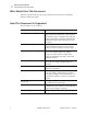
About This Document Who Should Use This Document Who Should Use This Document This User Guide is intended for use by any person who needs to operate or troubleshoot problems with the print engine. How This Document Is Organized The User Guide is set up as follows: Section Description Print Engine Basics on page 7 This chapter provides a high-level overview of the print engine and its components. A print engine is a printer that is part of a labeling system.
About This Document Contacts Contacts You can contact Zebra Technologies at any of the following: Visit us at: http://www.zebra.com Our Mailing Addresses: Zebra Technologies Corporation 333 Corporate Woods Parkway Vernon Hills, Illinois 60061.3109 U.S.A Telephone: +1 847.634.6700 Fax: +1 847.913.
About This Document Document Conventions Document Conventions The following conventions are used throughout this document to convey certain information: Alternate Color (online only) Cross-references contain links to other sections in this guide. If you are viewing this guide online, click the blue text to jump to its location. Command Line Examples All command line examples appear in Courier New font.
About This Document Related Documents Tools • Tells you what tools you need to complete a given task. Illustration Callouts Callouts are used when an illustration contains information that needs to be labeled and described. A table that contains the labels and descriptions follows the graphic. Figure 1 provides an example.
About This Document Related Documents Notes • ___________________________________________________________________ __________________________________________________________________________ __________________________________________________________________________ __________________________________________________________________________ __________________________________________________________________________ __________________________________________________________________________ _____________________
1 Print Engine Basics This chapter provides a high-level overview of the print engine and its components. A print engine is a printer that is part of a labeling system. The print engine is mounted in a applicator, which includes components to apply labels automatically as they are printed. Contents Print Engine Exterior View . . . . . . . . . . . . . . . . . . . . . . . . . . . . . . . . . . . . . . . . . . . . . . . . . 8 Front Panel. . . . . . . . . . . . . . . . . . . . . . . . . . . . . . . . . . . .
Print Engine Basics Print Engine Exterior View Print Engine Exterior View Print engines are available in a right-hand configuration (media moves from left to right, Figure 2) and a left-hand configuration (media moves from right to left, Figure 3). Figure 2 • Right-Hand (RH) Print Engine 1 2 4 3 Figure 3 • Left-Hand (LH) Print Engine 1 2 4 3 1 2 3 4 8 Power on/off switch Front panel Media door Electronics cover R110PAX4 User Guide 58981L-002 Rev.
Print Engine Basics Front Panel Front Panel All controls and indicators for the print engine are located on the front panel (Figure 4). The Liquid Crystal Display (LCD) shows operating status and feature parameters. The front panel buttons are used to control the print engine operations and to set parameters. The front panel lights (LEDs) indicate the print engine’s status.
Print Engine Basics Front Panel Table 1 • Front Panel Buttons (Continued) Button Description/Function CANCEL CANCEL functions only in Pause mode. Pressing CANCEL has these effects: • Cancels the label format that is currently printing. • If no label format is printing, the next one to be printed is canceled. • If no label formats are waiting to be printed, CANCEL is ignored. To clear the print engine’s entire label format memory, press and hold CANCEL until the DATA light turns off.
Print Engine Basics Front Panel Table 2 • Front Panel Lights (Continued) LED OFF Indicates ON Indicates FLASHING Indicates MEDIA (Yellow) Normal operation. Media properly loaded. Out of media. (Print engine is paused, LCD displays error message, and PAUSE light is ON). — RIBBON (Yellow) Normal operation. Ribbon properly loaded. Ribbon in while print engine is in direct thermal mode, or no ribbon loaded while print engine is in thermal transfer mode.
Print Engine Basics Power On/Off Switch Power On/Off Switch The power on/off switch is located on the top of the print engine housing, as shown in Figure 5. When this switch is placed in the On (I) position, the POWER light turns on, and the print engine automatically performs a Power-On Self Test (POST). For more information, see Power-On Self Test on page 142. Figure 5 • Print Engine Power Switch 12 R110PAX4 User Guide 58981L-002 Rev.
2 Getting Started This chapter provides the tasks that you must complete and the issues that you must consider before you load and configure your print engine. Contents Before You Begin . . . . . . . . . . . . . . . . . . . . . . . . . . . . . . . . . . . . . . . . . . . . . . . . . . . . . . . Unpack and Inspect the Print Engine. . . . . . . . . . . . . . . . . . . . . . . . . . . . . . . . . . . . . . . . Inspect the Print Engine. . . . . . . . . . . . . . . . . . . . . . . . . . . . . . . . . . . . . .
Getting Started Before You Begin Before You Begin Review this checklist, and resolve any issues before you begin setting up your print engine. When you are ready, continue with Print Engine Operation on page 31. Unpack and Inspect the Print Engine Have you unpacked the print engine and inspected it for damage? If you have not, see Unpack and Inspect the Print Engine on page 15.
Getting Started Unpack and Inspect the Print Engine Unpack and Inspect the Print Engine When you receive the print engine, immediately unpack and inspect it for shipping damage. Save all packing materials. Inspect the Print Engine Inspect the print engine for possible damage incurred during shipment: • Check all exterior surfaces for damage. • Raise the media door, and inspect the media compartment for damage to components.
Getting Started Print Engine Installation Print Engine Installation This section provides basic information for mounting the print engine into an applicator. The illustrations in this section show the print engine from different angles and include measurements and clearance needs. Requirements Stability When the print engine is mounted, the complete assembly must be physically stable. When the print engine is loaded with ribbon and media, the equipment must not become physically unstable.
Getting Started Print Engine Installation Figure 6 • Front View of Right-Hand Print Engine 58981L-002 Rev.
Getting Started Print Engine Installation Figure 7 • Right Side View of Right-Hand Print Engine 18 R110PAX4 User Guide 58981L-002 Rev.
Getting Started Print Engine Installation Figure 8 • Rear View of Right-Hand Print Engine 58981L-002 Rev.
Getting Started Print Engine Installation Figure 9 • Top View of Right-Hand Print Engine 20 R110PAX4 User Guide 58981L-002 Rev.
Getting Started Print Engine Installation Install the Print Engine in an Applicator This section provides the basic instructions for installing the print engine into an applicator. Caution • If the print engine is installed improperly, it could fall out of the applicator and cause injury. The center mounting bolt and four mounting screws must be installed and secured. See Figure 10 for the location of the bolt and screws. To install the print engine into an applicator, complete these steps: 1.
Getting Started Connect the Print Engine to a Power Source Connect the Print Engine to a Power Source The power supply in the print engine automatically detects the applied line voltage and works in the 90 to 264 VAC, 48 to 62 Hz range. Refer to Figure 11. The AC power cord must have a three-prong female connector on one end that plugs into the mating AC power connector at the rear of the print engine. If a power cable was not included with your print engine, refer to Power Cord Specifications on page 23.
Getting Started Connect the Print Engine to a Power Source Power Cord Specifications Depending on how your print engine was ordered, a power cord may or may not be included. If one is not included or if the one included is not suitable for your requirements, refer to the following guidelines: • The overall cord length must be less than 9.8 ft (3.0 m). • The cord must be rated for at least 5 A, 250 V. • The chassis ground (earth) must be connected to ensure safety and reduce electromagnetic interference.
Getting Started Select a Communication Interface Select a Communication Interface The way that you connect your print engine to a data source depends on the communication options installed in the print engine. See Data Ports on page 157 for control signal descriptions and other additional information. Caution • Connecting a data communications cable while the power is ON may damage the print engine. Note • You must supply all interface cables for your application.
Getting Started Select a Communication Interface Optional Print Servers • • ZebraNet Wireless Print Server. For more information on this option, see the ZebraNet Wireless Print Server User Guide (part number 13422L-001). ZebraNet 10/100 Print Server (10/100 PS). For more information on 10/100 PS, see the ZebraNet 10/100 Print Server User and Reference Guide (part number 47619L-001).
Getting Started Select a Communication Interface Data Cable Requirements Data cables must be fully shielded and fitted with metal or metallized connector shells. Shielded cables and connectors are required to prevent radiation and reception of electrical noise. To minimize electrical noise pickup in the cable: • Keep data cables as short as possible. • Do not bundle the data cables tightly with the power cords. • Do not tie the data cables to power wire conduits.
Getting Started Types of Media Types of Media The print engine can use various types of media (Table 3). We strongly recommend the use of Zebra-brand supplies for continuous high-quality printing. A wide range of paper, polypropylene, polyester, and vinyl stock has been specifically engineered to enhance the printing capabilities of the printer and to ensure against premature printhead wear.
Getting Started Types of Media Table 3 • Types of Media (Continued) Media Type How It Looks Description Fanfold Media The media is folded in a zigzag pattern. RFID “Smart” Media (for use with RFID-capable print engines only) Each label has a radio frequency identification (RFID) chip and antenna inlay embedded between the label and the liner. The media is made from the same materials and adhesives as non-RFID labels.
Getting Started Ribbon Ribbon Ribbon is a thin film that is coated on one side with wax or wax resin, which is transferred to the media during the thermal transfer process. The media determines whether you need to use ribbon and how wide the ribbon must be. When ribbon is used, it must be as wide as or wider than the media being used. If the ribbon is narrower than the media, areas of the printhead are unprotected and subject to premature wear.
Getting Started Ribbon Adhesive Test If you have labels available, perform the adhesive test to determine which side of a ribbon is coated. This method works well for ribbon that is already installed. To perform an adhesive test, complete these steps: 1. Peel a label from its liner. 2. Press a corner of the sticky side of the label to the outer surface of the roll of ribbon. 3. Peel the label off of the ribbon. 4. Observe the results.