
User's Manual Part 2
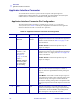
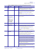
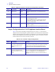
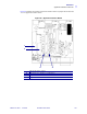
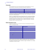
Table Of Contents

134 R110PAX3 User Guide 9/7/2004 58981L-001 Rev. 1
Data Ports
Applicator Interface Connector
Jumper Configurations for +5 V I/O Applicator Interface Board
Table 19 shows the pin and jumper configurations for pins 1 and 2 in +5 V I/O operation.
Jumpers J4 and J5 are used together to produce isolated or non-isolated modes of operation for
applicator input and output control signals. J4 configures the +5 V source for the optoisolator
circuits, and J5 configures the ground. For proper operation, when J4 is installed, J5 must be
installed, and when J4 is removed, J5 must be removed.
12 MEDIA OUT Output Asserted LOW while there is no media in the print
engine.
13 RIBBON OUT Output Asserted LOW while there is no ribbon in the print
engine.
14 DATA READY Output Asserted LOW when sufficient data has been received to
begin printing the next label.
De-asserted HIGH whenever printing stops after the
current label, due to either a pause condition or the
absence of a label format.
15 VOID Output Asserted LOW when the RFID transponder over the
antenna is “voided.”
De-asserted HIGH when the end print signal is asserted.
Table 18 • Applicator Interface Connector Pin Configuration (Continued)
Pin No. Signal Name Signal Type Description
Table 19 • Pin 1 and Pin 2 Jumper Configurations
Pin No. Non-Isolated Isolated
1 J5 In
I/O ground is connected to the
Applicator Interface Circuit
Ground.
J5 Out
I/O ground is disconnected from the Applicator Interface
Circuit Ground. Ground for the applicator interface
optoisolator circuits is provided externally to this pin.
2 J4 In
+5 V I/O is connected to the
Applicator Interface Circuit +5 V
Supply.
J4 Out
+5 V I/O is disconnected from the Applicator Interface
Circuit +5 V Supply. The +5 V for the applicator
interface optoisolator circuits is provided externally to
this pin.