
User's Manual
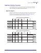
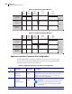
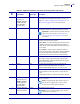
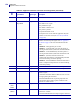
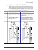
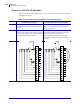
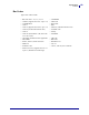
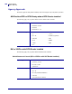
Table Of Contents

Data Ports
Applicator Interface Connector
152
13383L-002 Rev. A XiIIIPlus/R110Xi/R170Xi User Guide 12/2/05
Figure 65 • Applicator Signals (Mode 3)
Figure 66 • Applicator Signals (Mode 4)
Applicator Interface Connector Pin Configuration
The Applicator Interface Assembly is available in two versions: a +5 V I/O and a +24–
28 V I/O. Table 20 lists the pin configurations and functions of the applicator interface
connector for both +5 V and 24–28 V operation.
DATA READY
(pin 14)
START PRINT
(pin 3)
END PRINT
(pin 11)
label
format
sent
label
format
processed
waiting
for start
print signal
label
prints
ready
for next
label
n
ot rea
dy
r
ead
y
do
n
o
t
s
t
a
r
t
s
t
a
r
t
do
n
o
t
e
n
d
e
n
d
DATA READY
(pin 14)
START PRINT
(pin 3)
END PRINT
(pin 11)
label
format
sent
label
format
processed
waiting
for start
print signal
label
prints
ready
for next
label
n
ot rea
dy
r
ead
y
do
n
o
t
s
t
a
r
t
s
t
a
r
t
do
n
o
t
e
n
d
e
n
d
Table 20 • Applicator Interface Connector Pin Configuration
Pin
No.
Signal Name Signal Type Description
1 I/O SIGNAL
GROUND
(+5V Return)
I/O Signal
Ground
Using jumper J5, this pin can be configured as isolated or
non-isolated from the printer signal ground. See Jumper
Configurations and Pinouts for +5 V I/O Operation
on page 155 for more information.
1 I/O SIGNAL
GROUND
(+24-28V Return)
I/O Signal
Ground
No jumpers to configure.
Important • Customer must provide this external
ground (can come from pin 8). See Pinouts for
+24-28 V I/O Operation on page 156 for more
information.