
User Manual

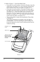

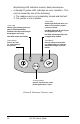
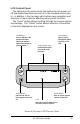

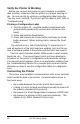

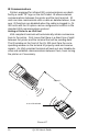
Table Of Contents
- Contents
- Introduction
- Unpacking and Inspection
- Reporting Damage
- Getting Ready to Print
- Battery
- Installing the Battery
- Charging the Battery
- Loading the Media
- Installing the Media
- Operator Controls
- Standard Keypad
- LCD Control Panel
- Verify the Printer Is Working
- Printing a Configuration Label
- Connecting the Printer
- Cable Communications
- IR Communications
- SRRF Communications
- Zebra SRRF Network Overview
- Bluetooth™ Networking Overview
- Wireless Local Area Network (WLAN) Module Using CF Radio
- Wireless Local Area Network (WLAN) Module Using PCMCIA Radio
- Setting Up the Software
- Adjustable Shoulder Strap
- Belt Clip
- Preventive Maintenance
- Extending Battery Life
- Cleaning
- Troubleshooting
- Standard Control Panel
- Optional LCD Control Panel
- Troubleshooting Topics
- Troubleshooting Tests
- Printing a Configuration Label
- Sample Configuration Label
- Communications Diagnostics
- Calling the Help Desk
- Specifications
- Printing Specifications
- Memory/Communications Specifications
- Label Specifications
- Font/Bar Code Specifications
- Physical/Environmental/Electrical Specifications
- Communications Port
- _
- Agency Approvals
- Accessories
- Appendix A
- Interface Cables
- _
- Appendix B
- Media Supplies
- Appendix C
- Maintenance Supplies
- Appendix D
- Product Support
- Index 49
- Patent Information

QL 320 User’s Guide 11
2. Load the media: Refer to Figure 5.
•Determine that the core diameter of the media roll match-
es the setting of the Media Disks. If it does not, adjust the
media disks per Figure 6 below.
• If the media support setting is correct, pull the media sup-
ports apart, insert the roll of media between them, and let
the media supports close. Insure that the media pulls off
the core in the direction
shown in Figure 5. The
supports will adjust
themselves to the
width of the media,
and the media
should be able to
spin freely on the
supports.
continued on next page
FIGURE 5
Media Roll
Note direction
media pulls off the
roll.
Media Disk
must match
diameter of
Media Core.
FIGURE 6
Media Disk set for 3/4”
core (factory default).
Remove Media Disk,
rotate 180° and replace
for 1
3
/
8
” core