
User's Manual

Beacon Hardware Specifications and Installation 2 - 15
Beacon Hardware Specifications and Installation 2 - 15
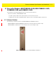
2.8 Beacon Part Number: GE-MB1000-01-WR
A GE-MB1000-01-WR beacon is a smaller beacon designed to be afixed to assets.
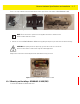
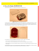
Figure 2-17 GE-MB1000-01-WR and Mounting Accessory
The above image depicts a GE-MB1000-01-WR asset beacon and the mounting accessory (GE-MB1000-01-ACC) used to attach
the asset beacon to an object lacking a flat mounting surface or space. On the side of the asset beacon is a switch used to
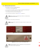
place the device in different operating modes. The following image is a rear view of the asset beacon displaying the adhesive
strip used to attach the asset beacon to any flat surface or to the mounting accessory.
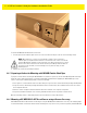
Figure 2-18 GE-MB1000-01-WR and Adhesive Strip
As a prerequisite, to mounting a GE-MB1000-01-WR model asset beacon, adhere to the following:
• The asset beacon should ideally be mounted on any flat, smooth, dry surface.
• There should be no structures immediately in front or to the sides that would block signals from this unit.
• Before peeling the cover off the mounting tape, hold the asset beacon in its intended mounting location and ensure it will
fit as desired.
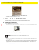
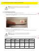
The following image is a view of the asset beacon attached to a laboratory device. The antenna pattern is omni-directional and
the unit operates sufficiently in any vertical orientation. The preferred orientation is as shown: