MPACT LOCATION & ANALYTICS Hardware Installation Guide MB1000 ATLS-T1B MB2000 MPact-INDR1 MB3000 MPact-USB1 MB4000 MPact-OUTR1 GE-MB1000-01-WR GE-MB2001-01-WR GE-MB4001-01-WR GE-MB5000-01-WR GE-MB6000-01-WR Badge GE-MB6000-CHRGR MN00XXXXA01
TABLE OF CONTENTS Chapter 1 MPact Bluetooth® Smart beacon Overview Chapter 2 Beacon Hardware Specifications and Installation 2.1 MB1000 Beacon Part Number: MPACT-T1B20-000-WR ...............................................................................................2-1 2.1.1 Installing the Tie-Wrap Style Beacon ..................................................................................................................2-2 2.2 MB1000 Beacon Part Number: MPACT-T1B10-000-WR ...........................
MPact Location & Analytics Hardware Installation Guide Appendix A Customer Support
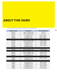
ABOUT THIS GUIDE This guide supports the following product families, parts and regulatory models:
MPact Location & Analytics Hardware Installation Guide This chapter is organized into the following sections: • Using the Documentation • Zebra Technologies Corporation ("Zebra") End-User Software License Agreement
Using the Documentation The following sections provide information about the document and notational conventions used in the guides, and provides a list of related documentation. Document Conventions The following conventions are used in this manual to draw your attention to important information: NOTE: Indicates tips or special requirements. ! CAUTION: Indicates conditions that can cause equipment damage or data loss.
MPact Location & Analytics Hardware Installation Guide Notational Conventions The following notational conventions are used in this document: • Italics are used to highlight specific items in the general text, and to identify chapters and sections in this and related documents • Bullets (•) indicate: • lists of alternatives • lists of required steps that are not necessarily sequential • action items • Sequential lists (those describing step-by-step procedures) appear as numbered lists Related Documenta
Zebra Technologies Corporation ("Zebra") End-User Software License Agreement BY INSTALLING AND/OR USING THIS PRODUCT, YOU ACKNOWLEDGE THAT YOU HAVE READ THIS AGREEMENT, UNDERSTAND IT AND AGREE TO BE BOUND ITS TERMS. IF YOU DO NOT AGREE TO THE TERMS OF THIS AGREEMENT, ZEBRA IS NOT WILLING TO LICENSE THE PRODUCT TO YOU, AND YOU MUST NOT INSTALL OR USE THIS PRODUCT.
MPact Location & Analytics Hardware Installation Guide CORRECTNESS, ACCURACY, OR RELIABILITY OF THE PRODUCTS. Some jurisdictions do not allow the exclusion of implied warranties, so the above exclusion may not apply to you. Limitation of Liability THE TOTAL LIABILITY OF ZEBRA UNDER THIS AGREEMENT FOR DAMAGES SHALL NOT EXCEED THE FAIR MARKET VALUE OF THE PRODUCTS LICENSED UNDER THIS AGREEMENT.
Governing Law This Agreement shall be governed by the laws of the United States of America to the extent that they apply and otherwise by the laws of the State of New York without regard to its conflict of laws provisions or by the internal substantive laws of the country to which the Products is shipped if end-user customer is a sovereign governmental entity. The terms of the U.N. Convention on Contracts for the International Sale of Goods do not apply.
MPact Location & Analytics Hardware Installation Guide
CHAPTER 1 MPACT BLUETOOTH® SMART BEACON OVERVIEW MPact utilizes Bluetooth® Smart beacons in various modes to unify Wi-Fi and Bluetooth® Smart Technology to capture analytics, accuracy and insight. Beacon placements can be adjusted within a deployment floor plan, and depending on the mode selected, their battery life can be tracked over time. Administrators can cursor over a beacon on a site’s floor plan to assess the beacon’s remaining battery life.
1 - 2 MPact Location & Analytics Hardware Installation Guide 1.
CHAPTER 2 BEACON HARDWARE SPECIFICATIONS AND INSTALLATION The following setup processes must be completed as a prerequisite to installing beacon hardware: • MPact Server Installation and Setup - see the MPact Location & Analytics Deployment Guide • MPact Toolbox and Beacon Installation - see the MPact Toolbox User Guides The guides are available at www.zebra.com/support.
2 - 2 MPact Location & Analytics Hardware Installation Guide 2.1.1 Installing the Tie-Wrap Style Beacon Tie-wrap beacon housings are designed to attach to vertical or horizontal poles or similar mounting surfaces. In Figure 2-1, there are openings on the back of the beacon housing allowing a tie wrap through the openings and wrapped around a pole or similar structure. Notice the up arrow located on the middle of the beacon housing.
Beacon Hardware Specifications andInstallation Installation 22--33 Beacon Hardware Specifications and 2.
2 - 4 MPact Location & Analytics Hardware Installation Guide To mount the universal style beacon to Lozier® Shelves: 1. Mount the universal beacon shelf-bracket on the shelf: • Metal brackets: Fit in place and tighten onto the shelving unit using a phillips-head screw driver. • Plastic brackets: Fit in place and snap onto the shelving unit. 2. Fit the beacon’s universal style housing into the bracket (mylar strip pointing up) and turn the beacon housing clockwise 90 degrees.
Beacon Hardware Specifications andInstallation Installation 22--55 Beacon Hardware Specifications and Activate one or MPACT-T1B10-000-WR model beacons by pulling the mylar strip off the beacon housing. CAUTION: After pulling off the last mylar strip, you have 20 seconds to associate the beacon in either offline or online mode using the Toolbox application. 2.2.2 Beacon Battery Replacement When a beacon’s battery life is less than 20%, the beacon should be prioritized for immediate replacement.
2 - 6 MPact Location & Analytics Hardware Installation Guide 4. Remove the old battery, dispose properly, and replace with a Panasonic CR2450 model battery. NOTE: Pay attention to the position of the + on the battery. Installing the battery backwards may damage the Beacon 5. Close the tray, ensuring the latch is secure. 2.
Beacon Hardware Specifications andInstallation Installation 22--77 Beacon Hardware Specifications and There is one style of bracket mount included with the Indoor Style Beacon: Part number - MPACT-MB2000-01-WR. Figure 2-7 Metal Beacon Wall Mount Bracket: MPACT-MB2000-01-WR NOTE: Ensure the beacon is positioned correctly, Once the beacon is mounted on the bracket it will be difficult to remove. 2.
2 - 8 MPact Location & Analytics Hardware Installation Guide Figure 2-9 GE-MB2001-01-WR Cover and Wall Mount
Beacon Hardware Specifications andInstallation Installation 22--99 Beacon Hardware Specifications and 2.4 Beacon Operating Modes Refer to the following for beacon operating modes for MPACT-MB2000-01-WR, GE-MB2000-01-WR and GE-MB1000-01-WR model beacons: Mode Definition Sleep The beacon is not transmitting or accepting client connections. Configuration The beacon accepts connections from clients. Clients can configure the device when connected.
2 - 10 MPact Location & Analytics Hardware Installation Guide Figure 2-10 Open Battery Enclosure: MPACT-MB2000-01-WR 4. Close the battery enclosure, ensuring the clip is secure. 2.6 USB Beacon Part Number: MPACT-MB3000-01-WR A USB powered interface is required to power the USB Beacon. No additional hardware is required. 2.6.1 Installing the USB Style Beacon To activate a MPACT-MB3000-01-WR model beacon: 1. Insert the beacon into any standard USB power source.
Beacon Hardware Specifications andInstallation Installation 2 2- -11 11 Beacon Hardware Specifications and 2.7 Beacon Part Numbers: MPACT-MB4000-01-WR, MPACT-MB4001-01-WR, GE-MB4000-01-WR and GE-MB4001-01-WR As a prerequisite, the following hardware items are required to mount a beacon. • Beacon: Part numbers - MPACT-MB4000-01-WR • Two No. 6 gauge or M3.5 screws (not included) for use on the intended surface • Phillips head screw driver compatible with No.
2 - 12 MPact Location & Analytics Hardware Installation Guide Figure 2-13 Antennae Positions for the GE-MB4000-01-WR Beacon (TBD) 2.7.2 Mounting and Installing the Outdoor Style Beacon 1. From the MPact Toolbox, select a site floor plan and an unassigned position for the beacon. Refer to the MPact Location & Analytics Deployment Guide for information on how to install and deploy the beacon from the Toolbox. To prepare the Outdoor style beacon for mounting: .
Beacon Hardware Specifications andInstallation Installation 2 2- -13 13 Beacon Hardware Specifications and 2.7.2.2 Mounting Outdoor Style Beacon To mount a Outdoor Style beacon with 3M™ VHB™ tape: 1. Peel the plastic off from 3M™ VHB™ tape. 2. Press the backside of the Outdoor Style beacon firmly to a smooth clean mounting surface. To mount a Outdoor Style beacon with No. 6 gauge or M3.5 screws: 1. Press the backside of the beacon to the mounting surface. 2.
2 - 14 MPact Location & Analytics Hardware Installation Guide NOTE: When installing numerous beacons, group beacons by category configurations and activate the beacons prior to scanning the barcodes and associating them with positions in the Toolbox. 2.7.2.3 Activating Outdoor Style Beacon To activate a MPACT-MB4000-01-WR or GE-MB1000-01-WR model beacon: 1. Swipe your finger across the capacitive switch several times to wake the beacon out of shipping mode into broadcast mode.
Beacon Hardware Specifications andInstallation Installation 2 2- -15 15 Beacon Hardware Specifications and 2.8 Beacon Part Number: GE-MB1000-01-WR A GE-MB1000-01-WR beacon is a smaller beacon designed to be afixed to assets. Figure 2-17 GE-MB1000-01-WR and Mounting Accessory The above image depicts a GE-MB1000-01-WR asset beacon and the mounting accessory (GE-MB1000-01-ACC) used to attach the asset beacon to an object lacking a flat mounting surface or space.
2 - 16 MPact Location & Analytics Hardware Installation Guide Figure 2-19 GE-MB1000-01-WR Preferred Orientation To mount a GE-MB1000-01-WR model asset beacon: 1. Peel the tape from the adhesive pads on the rear of the asset beacon and press the unit to the mounting surface. NOTE: Once adhered to a surface, its very difficult to remove. The asset beacon’s adhesive pads need replacement if moved to a new location. If the surface is clean and smooth, 3M VHB tape should be used to mount the asset beacon.
Beacon Hardware Specifications andInstallation Installation 2 2- -17 17 Beacon Hardware Specifications and 01 asset beacon. The beacon is attached to the mounting plastic using the adhesive strip, then a tie wrap is used to connect the mounting plastic to the hand tool. Figure 2-20 GE-MB1000-01-ACC Beacon Accessory To mount the asset beacon using the GE-MB1000-01-ACC beacon accessory: NOTE: The beacon can also be mounted using a lanyard or zip tie. 1.
2 - 18 MPact Location & Analytics Hardware Installation Guide 2. Once adhered to the beacon accessory, it can be attached to other items using a lanyard or zip tie placed through the slot in the surfboard. 2.8.3 GE-MB1000-01-WR Operating Modes Refer to the following for operating modes for GE-MB1000-01-WR asset beacon operating modes: Mode Definition Sleep The beacon is not transmitting or accepting client connections. Configuration The beacon accepts connections from clients.
Beacon Hardware Specifications andInstallation Installation 2 2- -19 19 Beacon Hardware Specifications and 2.9 Beacon Part Number: GE-MB2001-01-WR As a prerequisite, to mounting a GE-MB2001-01-WR model beacon, adhere to the following: • Do not install the cover on the unit until the beacon has been initialized and configuration verified. • Ensure the planned installation location matches your physical deployment plans. • Beacon mounting heights may vary, but should be about 5' from the floor.
2 - 20 MPact Location & Analytics Hardware Installation Guide Figure 2-23 GE-MB2001-01-WR Beacon Cover NOTE: Once adhered to a surface, its very difficult to remove. The beacon’s adhesive pads will need to be replaced if it is moved to a new location.
Beacon Hardware Specifications andInstallation Installation 2 2- -21 21 Beacon Hardware Specifications and 2.10 Initializing a GE-MB5000-01-WR Hub A GE-MB5000-01-WR (or hub) scans for Bluetooth smart beacon emissions. The hub filters based on its scanning configuration for known devices and forwards scan results to its defined administration (posting) server. The hub ships with a default software load, but without its configuration.
2 - 22 MPact Location & Analytics Hardware Installation Guide Figure 2-25 GE-MB5001-01-WR • Reboot the badge - Press and hold button 2 between 10 and 20 seconds, then release. LED 1 will blink slowly twice to confirm. Any in-process configuration activity will need to be re-started. • Erase to factory default configuration and reboot - Press and hold button 2 between 30 and 40 seconds, then release. LED 1 will blink slowly twice to confirm.
Beacon Hardware Specifications andInstallation Installation 2 2- -23 23 Beacon Hardware Specifications and 2.11 Beacon Part Number: GE-MB6000-01-WR Badge A GE-MB6000-01-WR badge is a wearable beacon that’s clipped to one’s body, typcially in the mid section or belt area. NOTE: The clip portion of the badge is a replaceable part, GE-MB6000-01-ACC. Refer to Part No. GE-MB6000-01-ACC when ordering a replacement clip to a GE-MB6000-01-WR model badge. To mount a GE-MB6000-01-WR model badge: 1.
2 - 24 MPact Location & Analytics Hardware Installation Guide 2.11.1 GE-MB6000-01-WR Battery Safety Precautions 2.11.1.1 When Using a GE-MB6000-01 Battery Misusing the battery may cause the battery to get hot, rupture or ignite causing serious injury. Be sure to follow the safety rules listed below: • Do not place the battery in fire or heat the battery. • Do not install the battery backwards so that the polarity is reversed.
Beacon Hardware Specifications andInstallation Installation 2 2- -25 25 Beacon Hardware Specifications and 2.11.1.3 Discarding a GE-MB6000-01 Battery Do not discharge the battery using and device except its designated device. When the battery is used in devices aside from its designated device it may damage the performance of the battery and potentially reduce its useful expectancy.
2 - 26 MPact Location & Analytics Hardware Installation Guide Voltage 5Vdc +/- 5% Current Each Badge requires 900 mA during charging, total 5Vdc power is 10 Amps Power Consumption 50-60 Watts Power Supply External 12 Vdc, 5 Amps max, 60 watts total, enclosed power supply Power Cord AC power cord connecting external power supply to AC power Power Supply Connector Barrel connector (2.5mm outside diameter). The plastic enclosure has built-in strain relief to prevent accidental disconnects.
Beacon Hardware Specifications andInstallation Installation 2 2- -27 27 Beacon Hardware Specifications and • Do not use incompatible batteries and chargers. Use of an incompatible battery or charger may present a risk of fire, explosion, leakage or other hazard. If you have any questions about the compatibility of a battery or a charger, contact Zebra Support.
2 - 28 MPact Location & Analytics Hardware Installation Guide 7. Allow at least 10 to 30 minutes (depending on ambient temperature and humidity) for the alcohol to air dry before applying power to cradle. If the temperature is low and the humidity is high, a longer drying time is required. Warm temperatures and dry humidity require less drying time. 2.12.
APPENDIX CUSTOMER SUPPORT If you have a problem with your equipment, contact Support for your region. Support and issue resolution is provided for products under warranty or that are covered by a services agreement. Contact information and Web self-service is available by visiting www.zebra.com/support.
A - 2 MPact Location & Analytics Hardware Installation Guide
MN00XXXXA01 DRAFT July, 2016