MPACT LOCATION & ANALYTICS MB1000 ATLS-T1B MB2000 MPact-INDR1 MB3000 MPact-USB1 MB4000 MPact-OUTR1 GE-MB1000-01-WR GE-MB2001-01-WR GE-MB4001-01-WR GE-MB5000-01-WR GE-MB6000-01-WR Badge GE-MB6000-CHRGR Hardware Installation Guide MN-002947-01
MPact Location & Analytics Hardware Installation Guide 2 MN-002947-01
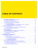
TABLE OF CONTENTS 1.1 Product and Part Compatibility Matrix ..........................................................................................................................1-2 2.1 MB1000 Beacon Part Number: MPACT-T1B20-000-WR ...............................................................................................2-3 2.1.1 Installing the Tie-Wrap Style Beacon ..................................................................................................................2-4 2.
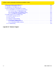
MPact Location & Analytics Hardware Installation Guide 2.9 Beacon Part Number: GE-MB2001-01-WR ..................................................................................................................2-23 2.10 Installing a GE-MB5000-01-WR Hub .........................................................................................................................2-25 2.11 Initializing a GE-MB5000-01-WR Hub ..............................................................................................
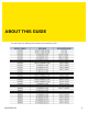
ABOUT THIS GUIDE This guide supports the following product families, parts and regulatory models: MN-002947-01 5
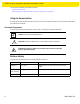
MPact Location & Analytics Hardware Installation Guide This chapter is organized into the following sections: • Using the Documentation • Zebra Technologies Corporation ("Zebra") End-User Software License Agreement Using the Documentation The following sections provide information about the document and notational conventions used in the guides, and provides a list of related documentation.
MPact Location & Analytics Hardware Installation Guide Notational Conventions The following notational conventions are used in this document: • Italics are used to highlight specific items in the general text, and to identify chapters and sections in this and related documents • Bullets (•) indicate: • lists of alternatives • lists of required steps that are not necessarily sequential • action items • Sequential lists (those describing step-by-step procedures) appear as numbered lists Related Documentatio
MPact Location & Analytics Hardware Installation Guide Zebra Technologies Corporation ("Zebra") End-User Software License Agreement BY INSTALLING AND/OR USING THIS PRODUCT, YOU ACKNOWLEDGE THAT YOU HAVE READ THIS AGREEMENT, UNDERSTAND IT AND AGREE TO BE BOUND ITS TERMS. IF YOU DO NOT AGREE TO THE TERMS OF THIS AGREEMENT, ZEBRA IS NOT WILLING TO LICENSE THE PRODUCT TO YOU, AND YOU MUST NOT INSTALL OR USE THIS PRODUCT.
MPact Location & Analytics Hardware Installation Guide CORRECTNESS, ACCURACY, OR RELIABILITY OF THE PRODUCTS. Some jurisdictions do not allow the exclusion of implied warranties, so the above exclusion may not apply to you. Limitation of Liability THE TOTAL LIABILITY OF ZEBRA UNDER THIS AGREEMENT FOR DAMAGES SHALL NOT EXCEED THE FAIR MARKET VALUE OF THE PRODUCTS LICENSED UNDER THIS AGREEMENT.
MPact Location & Analytics Hardware Installation Guide Governing Law This Agreement shall be governed by the laws of the United States of America to the extent that they apply and otherwise by the laws of the State of New York without regard to its conflict of laws provisions or by the internal substantive laws of the country to which the Products is shipped if end-user customer is a sovereign governmental entity. The terms of the U.N.
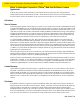
OVERVIEW MPact utilizes Bluetooth® Smart beacons in various modes to unify Wi-Fi and Bluetooth® Smart Technology to capture analytics, accuracy and insight. Beacon placements can be adjusted within a deployment floor plan, and depending on the mode selected, their battery life can be tracked over time. Administrators can cursor over a beacon on a site’s floor plan to assess the beacon’s remaining battery life.
MPact Location & Analytics Hardware Installation Guide 1.
BEACON HARDWARE SPECIFICATIONS AND INSTALLATION The following setup processes must be completed as a prerequisite to installing beacon hardware: • MPact Server Installation and Setup - see the MPact Location & Analytics Deployment Guide • MPact Toolbox and Beacon Installation - see the MPact Toolbox User Guides The guides are available at www.zebra.com/support.
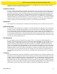
MPact Location & Analytics Hardware Installation Guide 2.1.1 Installing the Tie-Wrap Style Beacon Tie-wrap beacon housings are designed to attach to vertical or horizontal poles or similar mounting surfaces. In Figure 2-1, there are openings on the back of the beacon housing allowing a tie wrap through the openings and wrapped around a pole or similar structure. Notice the up arrow located on the middle of the beacon housing. This arrow indicates the optimal orientation for the beacon to function properly.
MPact Location & Analytics Hardware Installation Guide 2.
MPact Location & Analytics Hardware Installation Guide To mount the universal style beacon to Lozier® Shelves: 1. Mount the universal beacon shelf-bracket on the shelf: • Metal brackets: Fit in place and tighten onto the shelving unit using a Phillips-head screw driver. • Plastic brackets: Fit in place and snap onto the shelving unit. 2. Fit the beacon’s universal style housing into the bracket (mylar strip pointing up) and turn the beacon housing clockwise 90 degrees.
MPact Location & Analytics Hardware Installation Guide Activate one or MPACT-T1B10-000-WR model beacons by pulling the mylar strip off the beacon housing. CAUTION: After pulling off the last mylar strip, you have 20 seconds to associate the beacon in either off-line or on-line mode using the Toolbox application. 2.2.2 Beacon Battery Replacement When a beacon’s battery life is less than 20%, the beacon should be prioritized for immediate replacement.
MPact Location & Analytics Hardware Installation Guide 4. Remove the old battery, dispose properly, and replace with a Panasonic CR2450 model battery. NOTE: Pay attention to the position of the + on the battery. Installing the battery backwards may damage the Beacon 5. Close the tray, ensuring the latch is secure. 2.
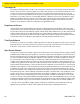
MPact Location & Analytics Hardware Installation Guide There is one style of bracket mount included with the Indoor Style Beacon: Part number - MPACT-MB2000-01-WR. Figure 2-7 Metal Beacon Wall Mount Bracket: MPACT-MB2000-01-WR NOTE: Ensure the beacon is positioned correctly, Once the beacon is mounted on the bracket it will be difficult to remove. 2. Activate one or more MPACT-MB2000-01-WR beacons by pulling the mylar strip out from inside the beacon housing.
MPact Location & Analytics Hardware Installation Guide 2.3.2 Mounting and Installing a GE-MB2001-01-WR To mount a GE- MB2001-01-WR model beacon ,use only the GE-MB2001-01-ACC housing. Please see the mounting instructions for this product in order to mount the GE-MB2000-01-WR. Clip the Beacon into the rear of the housing with the gray button on the right side as shown in this picture.
MPact Location & Analytics Hardware Installation Guide The cover can be removed to service the beacon by placing a small screwdriver into the gap on the right side as shown in the picture.
MPact Location & Analytics Hardware Installation Guide 2.4 Beacon Operating Modes Refer to the following for beacon operating modes for MPACT-MB2000-01-WR, GE-MB2000-01-WR and GE-MB1000-01-WR model beacons: Mode Definition Sleep The beacon is not transmitting or accepting client connections. Configuration The beacon accepts connections from clients. Clients can configure the device when connected.
MPact Location & Analytics Hardware Installation Guide Figure 2-12 Open Battery Enclosure: MPACT-MB2000-01-WR 4. Close the battery enclosure, ensuring the clip is secure. 2.6 USB Beacon Part Number: MPACT-MB3000-01-WR A USB powered interface is required to power the USB Beacon. No additional hardware is required. 2.6.1 Installing the USB Style Beacon To activate a MPACT-MB3000-01-WR model beacon: 1. Insert the beacon into any standard USB power source.
MPact Location & Analytics Hardware Installation Guide 2.7 Beacon Part Numbers: MPACT-MB4000-01-WR, MPACT-MB4001-01-WR, GE-MB4000-01-WR and GE-MB4001-01-WR As a prerequisite, the following hardware items are required to mount a beacon. • Beacon: Part numbers - MPACT-MB4000-01-WR • Two No. 6 gauge or M3.5 screws (not included) for use on the intended surface • Phillips head screw driver compatible with No. 6 gauge screws for mounting the Outdoor Style beacon 2.7.
MPact Location & Analytics Hardware Installation Guide Figure 2-15 Antennae Positions for the GE-MB4000-01-WR Beacon (TBD) 2.7.2 Mounting and Installing the Outdoor Style Beacon 1. From the MPact Toolbox, select a site floor plan and an unassigned position for the beacon. Refer to the MPact Location & Analytics Deployment Guide for information on how to install and deploy the beacon from the Toolbox. To prepare the Outdoor style beacon for mounting: .a Prepare a surface with 3M VHB double-sided tape.
MPact Location & Analytics Hardware Installation Guide 2.7.2.2 Mounting Outdoor Style Beacon To mount a Outdoor Style beacon with 3M™ VHB™ tape: 1. Peel the plastic off from 3M™ VHB™ tape. 2. Press the backside of the Outdoor Style beacon firmly to a smooth clean mounting surface. To mount a Outdoor Style beacon with No. 6 gauge or M3.5 screws: 1. Press the backside of the beacon to the mounting surface. 2. Insert screws into the screw holes as shown in Figure 2-17 on page 2-16.
MPact Location & Analytics Hardware Installation Guide NOTE: When installing numerous beacons, group beacons by category configurations and activate the beacons prior to scanning the barcodes and associating them with positions in the Toolbox. 2.7.2.3 Activating Outdoor Style Beacon To activate a MPACT-MB4000-01-WR or GE-MB1000-01-WR model beacon: 1. Swipe your finger across the capacitive switch several times to wake the beacon out of shipping mode into broadcast mode.
MPact Location & Analytics Hardware Installation Guide 2.8 Beacon Part Number: GE-MB1000-01-WR A GE-MB1000-01-WR beacon is a smaller beacon designed to be affixed to assets. Figure 2-19 GE-MB1000-01-WR and Mounting Accessory The above image depicts a GE-MB1000-01-WR asset beacon and the mounting accessory (GE-MB1000-01-ACC) used to attach the asset beacon to an object lacking a flat mounting surface or space.
MPact Location & Analytics Hardware Installation Guide Figure 2-21 GE-MB1000-01-WR Preferred Orientation To mount a GE-MB1000-01-WR model asset beacon: 1. Peel the tape from the adhesive pads on the rear of the asset beacon (as shown below) and press the unit to the mounting surface. Figure 2-22 GE-MB1000-01-WR Adhesive Tape NOTE: Once adhered to a surface, its very difficult to remove. The asset beacon’s adhesive pads need replacement if moved to a new location.
MPact Location & Analytics Hardware Installation Guide 2.8.1 Preparing a Surface for Mounting with 3M VHB Double-Sided Tape To prepare a surface before mounting the GE-MB1000-01 asset beacon style to any surface with 3M VHB double-sided tape: Clean the surface with a 50:50 mixture of isopropyl alcohol (IPA) and water before applying the 3M™ VHB™ tape.
MPact Location & Analytics Hardware Installation Guide Figure 2-24 GE-MB1000-01-ACC Beacon Accessory NOTE: Once adhered to a surface, its very difficult to remove. The beacon’s adhesive pads will need to be replaced if it is moved to a new location. The part number for replacement tape is GE-MB1000-TAPE. 2. Once adhered to the beacon accessory, it can be attached to other items using a lanyard or zip tie placed through the slot in the surfboard. 2.8.
MPact Location & Analytics Hardware Installation Guide The GE-MB1000-01-WR is delivered in shipping mode. To initiate beacon operation, press the button three times quickly. The LED flashes several times and the beacon begins to broadcast. Using the table below, hold the button for the length of time shown to change modes. The LED displays a different light pattern depending on the mode it is entering.
MPact Location & Analytics Hardware Installation Guide 2.9 Beacon Part Number: GE-MB2001-01-WR As a prerequisite, to mounting a GE-MB2001-01-WR model beacon, adhere to the following: • Do not install the cover on the unit until the beacon has been initialized and configuration verified. • Ensure the planned installation location matches your physical deployment plans. • Beacon mounting heights may vary, but should be about 5' from the floor. • Ensure the intended deployment location has WiFi coverage.
MPact Location & Analytics Hardware Installation Guide Figure 2-26 GE-MB2001-01-WR Beacon Cover NOTE: Once adhered to a surface, its very difficult to remove. The beacon’s adhesive pads will need to be replaced if it is moved to a new location.
MPact Location & Analytics Hardware Installation Guide 2.10 Installing a GE-MB5000-01-WR Hub Peel backing tape from adhesive on the back of the rear cover and place firmly on a wall. Make sure the arrow is pointing up and the power cord can reach from a nearby electrical outlet to the device. Screw holes can be used to mount the device (screws not provided) on very rough surfaces where adhesive tape is not recommended.
MPact Location & Analytics Hardware Installation Guide Insert the cable into the device and route according to the picture above. Exit the cable from the bottom edge and then snap the cover on, ensuring the any logo is correctly positioned and the small slot on the side is to the right.
MPact Location & Analytics Hardware Installation Guide Plug the power supply into an outlet and lug the USB end of the cable into the power supply.
MPact Location & Analytics Hardware Installation Guide 2.11 Initializing a GE-MB5000-01-WR Hub A GE-MB5000-01-WR (or hub) scans for Bluetooth smart beacon emissions. The hub filters based on its scanning configuration for known devices and forwards scan results to its defined administration (posting) server. The hub ships with a default software load, but without its configuration.
MPact Location & Analytics Hardware Installation Guide 2.12 Beacon Part Number: GE-MB6000-01-WR Badge A GE-MB6000-01-WR badge is a wearable beacon that’s clipped to one’s body, typically in the mid section or belt area. A GE-MB6000-01-WR badge needs to be to a person Add the following: The Badge is attached programmed in thein a manner directing RF radiation away from the body. The RF antennas radiate out from one side of the badge. A GE-MB6000-01-WR badge is designed to enhance personal safety.
MPact Location & Analytics Hardware Installation Guide Figure 2-33 GE-MB6000-01-WR: LEDs and Buttons NOTE: When the badge is facing you, the clip side facing you, button 1 is on the left top and button 2 is on the top right. • Reboot the badge - Press and hold button 2 between 10 and 20 seconds, then release. LED 1 will blink slowly twice to confirm. Any in-process configuration activity will need to be re-started.
MPact Location & Analytics Hardware Installation Guide 2.12.1 GE-MB6000-01-WR Battery Safety Precautions 2.12.1.1 When Using a GE-MB6000-01 Battery Misusing the battery may cause the battery to get hot, rupture or ignite causing serious injury. Be sure to follow the safety rules listed below: • Do not place the battery in fire or heat the battery. • Do not install the battery backwards so that the polarity is reversed.
MPact Location & Analytics Hardware Installation Guide 2.12.1.3 Discarding a GE-MB6000-01 Battery Do not discharge the battery using and device except its designated device. When the battery is used in devices aside from its designated device it may damage the performance of the battery and potentially reduce its useful expectancy. If the device causes an abnormal current flow it may result in the battery becoming hot, rapture or ignite resulting in serious injury.
MPact Location & Analytics Hardware Installation Guide 2.13 Cradle Charger: MPACT-MB6000-CHRGR 2.13.1 INITIAL CHARGING and USE When a brand new badge is received it should be inserted into the badge cradle before its initial use. The badge should be charged fully before its first use. The badge will automatically update its firmware and configuration profile if connected to the WiFi network and the gateway (if there is a profile update on the server).
MPact Location & Analytics Hardware Installation Guide The charger's primary function is providing 5Vdc at 900 mA to each badge holder re-charge badge batteries. The charger holds badges when not in use. When badges are in the charger, they begin to charge using the 5Vdc supplied in the charger base. If there is sufficient charge detected, the badge uses the charger as a holder (without charging).
MPact Location & Analytics Hardware Installation Guide 2.13.2 INSTALLATION The charger can we wall mounted using the screw holes on the back or placed on a flat surface. The screw holes are 5.36 inches (136 mm) apart. When selecting a deployment location, ensure the power adapter cables reach from the electrical outlet to the charger. The charger and its power adapter must be deployed in a well ventilated location.
MPact Location & Analytics Hardware Installation Guide 2.13.3 Battery Charging Guidelines Failure to follow these guidelines may result in fire, explosion or other hazard. • The area in which the units are charged should be clear of debris and combustible materials or chemicals. Particular care should be taken when charging in a non commercial environment. • To charge the battery, the battery and charger temperatures must be between 0 - 40 degrees Celsius. • Do not use incompatible batteries and chargers.
MPact Location & Analytics Hardware Installation Guide 2.13.4 Cleaning the Charging Cradle The following materials are required to clean the charging cradle: • Alcohol wipes • Cotton tipped applicators • Can of compressed air Cleaning is discretionary respect to the environments the(bleach) charger and the badges are deployed. They may be addfrequency the following: Wheninusing sodium hypochlorite based cleaned as frequently as required.
MPact Location & Analytics Hardware Installation Guide 2.13.
APPENDIX CUSTOMER SUPPORT If you have a problem with your equipment, contact Support for your region. Support and issue resolution is provided for products under warranty or that are covered by a services agreement. Contact information and Web self-service is available by visiting www.zebra.com/support.
MPact Location & Analytics Hardware Installation Guide 40 MN-002947-01
MPact Location & Analytics Hardware Installation Guide 41 MN-002947-01
MN-002947-01