
User's Manual


Setup and Deployment
29
MeshNetworks has developed the “Location Analyzer” tool to assist in the placement of
infrastructure. This tool runs on a Windows 2000 SD. The tool collects and analyzes data,
ultimately resulting in a deployment quality indication. Refer to the Location Analyzer
documentation for information on configuring and using this tool.
Antenna Guidelines
The location of fixed infrastructure antennas must address proper antenna orientation, selection
of elevation pattern for the specific locale, the avoidance of pattern distortion, and the impact of
obscuration and non-line-of-sight paths.
Polarization - Most of the antennas used in deployment will be vertically polarized. To maximize
line-of-sight signal reception, both the transmitting and receiving antennas should be vertically
oriented to avoid signal loss due to polarization mismatch. This applies to mobile and stationary
antennas. For example, placing a magnetically mounted vehicle antenna on a curved portion of
the vehicle roof so that its axis is not vertical risks a measure of signal loss at range, dependent
upon the specific elevation pattern details, as discussed above.
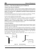
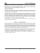
Local obstructions - Antennas should be mounted either above or below the plane of
obstructions as shown in Figure 28.
Figure 28. Antenna Mounting
Low gain “rubber duck” antennas that are mounted directly to Mesh transceivers are designed
for transmitting and receiving vertically polarized radiation. Hence, care must be taken to insure
close-to-vertical orientation of these antennas to avoid substantial signal loss due to polarization
mismatch. Additionally, attenuation sustained by use of these antennas inside vehicles can be
as high as 10 dB. Typically, losses are in the 4 to 7 dB range if the antenna is above the “metal
can” of the vehicle so that radiation and reception occur at window level.
Lab Checkout. IAPs should be deployed first and verified as functional. Next the WRs should
be deployed in a “near to far” pattern; in other words, WRs that are 1 hop from an IAP should
be deployed first, followed by WRs that are 2 hops from an IAP, etc. This allows the
functionality of each WR to be determined at the time of installation, thus eliminating any extra
truck rolls to trouble-shoot a WR.