
User's Manual


Setup and Deployment
9
MWR6300 Assembly
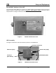
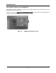
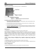
Figure 11 shows the external; connection points on a MWR6300 box.
Test Port
Figure 11. MWR6300 External Connection Points
Assemble the WR using the following procedure:
1. If desired, mount the WR box using the enclosed bracket. Refer to the procedure in the
IAP assembly section of this document.
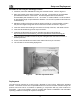
2. Insert the Antenna into the N-type Connector on the top of the box, and rotate to close.
3. Insert the Power Plug into the 4-pin Connector.
4. The transceiver MAC address is recorded on the back of the WR. Record this number in
Section 4 - MAC Address Tables
, as it will be required to configure and test the device.
5. The Test Port is unused during deployment.
Deployment
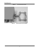
The MWR6300 can be mounted on a pole by using the provided bracket.
When deploying the MWR6300, the antenna should be a minimum of 30 inches from any
nearby metal poles to avoid distortion of the RF pattern. The antenna must have a separation
distance of at least 2 meters from the body of all persons and must not be co-located or
operating in conjunction with any other antenna or transmitter. Users and installers must be
provided with antenna installation and transmitter operating conditions to satisfy RF exposure
compliance.
Typically, wireless routers are distributed within a network to extend range and guarantee
coverage. A rule of thumb is to deploy 3-4 hop networks to optimize range, latency, and
throughput.
The MWR6300 installation location must provide AC power for the device.
It is the responsibility of the Network Operator to ensure that the installation complies with any
local building codes and permits.
Initial Configuration
The optional configuration process for Geo-Location is the same as the IAP.