
User's Manual


Setup and Deployment
5
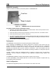
Assemble the IAP using the following procedure:
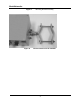
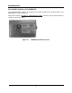
1. If desired, mount the IAP6300 box using the enclosed bracket. Refer to Figure 8.
2. Place the bracket at the desired position on the pole The bracket can accommodate
pole diameters between 1-3.5 inches. The bolts supplied with the bracket will
accommodate pole diameters of 2.75 – 3.5 inches. If needed, obtain a ¼-20 hex bolt of
an appropriate length for pole diameters between 1-2.75 inches (stainless steel bolts are
recommended).
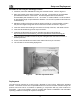
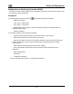
3. Adjust the position of the box so that the antenna will be in a vertical position. Tighten
the pivot and angle locking bolts on the shaft of the bracket as shown in Figure 9
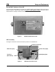
4. Insert the antenna into the N-type Connector on the top of the box, and rotate to close.
5. Insert the IAP Power Plug into the 4-pin connector.
6. Install the weatherproof connector on the Ethernet cable as described at:
http://www.siemon.com/installation_instructions/pdf/IMAXIndustrialUTPPlug.pdf
7. Insert the Ethernet Cable into the RJ-45 port and tighten the connector to ensure a
weatherproof seal.
8. If used, insert the Media Converter Power Cable into the 3-pin connector.
9. The Test Port is unused during deployment
6 x 32 x 3/4
Angle Locking Bolt
1/4 x 1 inch Pivot Bolt
(Requres 7/16 Wrench)
Figure 9. Bracket Adjustment Bolts
Deployment
The IAP may be mounted on a pole having a diameter of 1-3.5 inches, utilizing the provided
bracket. The antenna must have a separation distance of at least 2 meters from the body of all
persons and must not be co-located or operating in conjunction with any other antenna or
transmitter. Users and installers must be provided with antenna installation and transmitter
operating conditions to satisfy RF exposure compliance.