
User's Manual
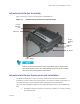
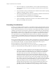

Table Of Contents
- _
- Chapter 1: Product Introduction
- HotZone Duo Infrastructure Devices
- IAPs and MWRs within a HOTZONE DUO Wireless Network
- HotZone Duo Infrastructure Device Specifications
- Chapter 2: Infrastructure Device Installation
- Software Requirements
- MWR and IAP Hardware Installation Notes
- _
- Equipment Specification
- Ports and Connections
- Operator Supply List
- Optional Antennas
- HotZone Duo Infrastructure Device Label
- Infrastructure Device MAC Address Table
- Infrastructure Device Assembly
- Infrastructure Device Deployment and Installation
- Grounding Considerations
- Assembling the IAP and the MWR Device
- Initial Infrastructure Device Configuration Information
- Device Connectivity Testing
- Chapter 3: Device Configuration
- Adding an Infrastructure Device in MeshManager
- Chapter 4: License Information
- Motorola End User License Agreement
- _
- Third Party Licensing Agreements
- OpenSSL - Copyright and License Information
- XSupplicant version 1.2.3 - Copyright and License Information
- Hostapd - Copyright and License Information
- Chapter 5: Customer Information
- Customer Service Information
- Obtaining Support
- System Information
- Return Material Request
- Radio Products and Services Division
- Radio Products and Services Division Telephone Numbers
- Returning System Components to Motorola
- Returning FREs
- Chapter 6: Certification and Safety Information
- FCC Regulatory Information
- Federal Communications Commission (FCC) Statement:
- FCC RF Radiation Exposure Statement
- Safety Information for the HOTZONE DUO Products
- Safety Certification

HotZone Duo 1.0 IAP and MWR Users Guide
2-7
• If the HotZone Duo product is attached to a light arm and the attachment point meets the
Type B grounding requirements, then the grounding stud attachment point is not
required to be used.
Assembling the IAP and the MWR Device
Use the following procedure to assemble an IAP and MWR Devices.
Procedure 2-1 Assembling the MWR and IAP Device
1
Place the brackets at the desired position on the pole.
2
Adjust the position of the box so that the antenna connecters are positioned vertically. Align the antennas
with the N-type connectors on the box and rotate to close.
3
Insert the cable into the external Ethernet port and tighten the connector to ensure a weatherproof seal.
4
Insert the Power Plug into the 4-pin connector.
Initial Infrastructure Device Configuration Information
Prior to attempting configuration of an IAP or an MWR device, the device must be powered up and
have connectivity to the MiSC.
Device Connectivity Testing
When a MiSC has been setup on the network, verify connectivity to the device using the following
procedure:
Procedure 2-2 Testing Infrastructure Device Connectivity
1
Apply power to the device, the device should be operation in 60 to 120 seconds
2
Obtain the 802.11 MAC addresses for the device subcomponents that were recorded in the MAC Address
Table earlier in this manual. The address will be in the format 02-05-12-30-xx-yy.
3
Within MeshManager’s Device Manager screen, right-click on the appropriate MWR or IAP device in
the Device Tree and select the Ping Device option.
4
Check for a successful response to the Ping command in the Named Device results dialog box. A
successful response to the ping commands verifies connectivity to the device (MWR or IAP).
5
Repeat steps 1-4 for additional MWR or IAP devices.
July 2006