
User's Manual

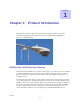
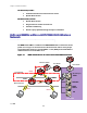
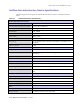

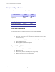
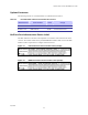
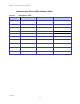
Table Of Contents
- _
- Chapter 1: Product Introduction
- HotZone Duo Infrastructure Devices
- IAPs and MWRs within a HOTZONE DUO Wireless Network
- HotZone Duo Infrastructure Device Specifications
- Chapter 2: Infrastructure Device Installation
- Software Requirements
- MWR and IAP Hardware Installation Notes
- _
- Equipment Specification
- Ports and Connections
- Operator Supply List
- Optional Antennas
- HotZone Duo Infrastructure Device Label
- Infrastructure Device MAC Address Table
- Infrastructure Device Assembly
- Infrastructure Device Deployment and Installation
- Grounding Considerations
- Assembling the IAP and the MWR Device
- Initial Infrastructure Device Configuration Information
- Device Connectivity Testing
- Chapter 3: Device Configuration
- Adding an Infrastructure Device in MeshManager
- Chapter 4: License Information
- Motorola End User License Agreement
- _
- Third Party Licensing Agreements
- OpenSSL - Copyright and License Information
- XSupplicant version 1.2.3 - Copyright and License Information
- Hostapd - Copyright and License Information
- Chapter 5: Customer Information
- Customer Service Information
- Obtaining Support
- System Information
- Return Material Request
- Radio Products and Services Division
- Radio Products and Services Division Telephone Numbers
- Returning System Components to Motorola
- Returning FREs
- Chapter 6: Certification and Safety Information
- FCC Regulatory Information
- Federal Communications Commission (FCC) Statement:
- FCC RF Radiation Exposure Statement
- Safety Information for the HOTZONE DUO Products
- Safety Certification

Chapter 2: Infrastructure Device Installation
2-2
July 2006
Equipment Specification
The specifications listed in the following table apply for all Infrastructure devices.
Table 2-2 HOTZONE DUO Infrastructure Device Radio Characteristics
Characteristic
2.4GHz
802.11 b/g
5.8GHz
802.11a
Output Power 30 dBm 30 dBm
RF Modulation CCK/OFDM OFDM
Operating Frequency (GHz) 2.4-2.4835 5.725-5.825
Maximum Burst Data Rate 54 Mbps 54 Mbps
Spectrum Used 20 MHz 20 MHz
Ports and Connections
The following list defines the standard ports and connections on IAPs and MWRs:
• Device Enclosure with 2 N-type Female Antenna Connector
• 120V A/C Power Cable with flying leads
• One RJ45. (On IAP devices only: External power supported on only one. Canopy
Connect POE Only.)
• On-board switch to supply power on Ethernet lines (for Canopy connectivity)
• Three pin RS232 connector
• Mounting Bracket (Standard and Optional)
Operator Supply List
The Network Operator must supply the following equipment:
• Mounting Location
• Power Source (120V A/C depending on IAP configuration)
• Ethernet connection between the IAP and MiSC.