M AP-6511 Access Point Installation Guide
MOTOROLA and the Stylized M Logo are registered in the US Patent & Trademark Office. Symbol is a registered trademark of Symbol Technologies, Inc. All other product or service names are the property of their respective owners. © Motorola, Inc. 2012. All rights reserved.
Table of Contents 1.0 Introduction . . . . . . . . . . . . . . . . . . . . . . . . . . . . . . . . . . . . . . . . . 1 1.1 Document Conventions . . . . . . . . . . . . . . . . . . . . . . . . . . . . . . . . . . 1 1.2 Warnings . . . . . . . . . . . . . . . . . . . . . . . . . . . . . . . . . . . . . . . . . . . . . 1 1.3 Site Preparation . . . . . . . . . . . . . . . . . . . . . . . . . . . . . . . . . . . . . . . 2 1.4 Package Contents . . . . . . . . . . . . . . . . . . . . . . . . . . . . . . . . . . . .
Introduction 1 Introduction The AP-6511 Access Point, a component of MotorolaSolutions Wireless Controller System, links wireless 802.11a/b/g/n devices to the controller, enabling the growth of your wireless network with a cost-effective alternative to standard access points. The AP-6511 is an enterprise class 802.11n access point, installed in minutes anywhere a CAT-5 (or better) cable is located. The AP-6511’s mechanical design is optimized for installation over a standard CAT-5 (or better) wall jack.
2 AP-6511 Access Point Installation Guide • • Verify any device connected to this unit is properly wired and grounded. Verify there is adequate ventilation around the device, and ambient temperatures meet equipment operation specifications. 1.3 Site Preparation • • • • • • Consult your site survey and network analysis reports to determine specific equipment placement, power drops etc. Assign installation responsibility to the appropriate personnel.
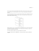
Introduction The access point contains runtime firmware which enables the unit to boot after either a power up or a watchdog reset. The runtime firmware on the access point can be updated via the Ethernet interface. The front of the AP-6511 has an access cover that can be removed to expose an additional connector. A three port RJ-45 Ethernet expansion module connects to the hidden header and snaps onto the AP-6511 in place of the access cover.
4 AP-6511 Access Point Installation Guide 2 Hardware Installation 2.1 Installation Instructions An AP-6511 access point mounts either on a wall, under a table or over a Telco Box. The AP-6511 is not plenum rated. NOTE The provided metal mounting plate is fastened to an existing standard Telco in-wall box. The box is customer provided within the customer building structure, and can be either plastic or metal in composition. Screws and other mounting hardware are not included.
Hardware Installation 2.3 Access Point Placement For optimal performance, install the access point away from transformers, heavy-duty motors, fluorescent lights, microwave ovens, refrigerators and other industrial equipment. Signal loss can occur when metal, concrete, walls or floors block transmission. Install the access point in an open area or add access points as needed to improve coverage.
6 AP-6511 Access Point Installation Guide • ! ! Ensure the cable length from the Ethernet source (host) to the Power Injector and AP-6511 access point does not exceed 100 meters (333 ft). CAUTION To avoid problematic performance and restarts, disable POE from a wired controller port connected to an access point if mid-span power sourcing equipment (PSE) is used between the two, regardless of the manufacturer.
Hardware Installation The screws used to mount the bracket are customer provided and should be #6, with a 2.00 inch length. 2. Connect one end of an RJ-45 cable into the wall mount connector on the AP-6511 as illustrated below.
8 AP-6511 Access Point Installation Guide 3. If using the optional second RJ-45 Ethernet port (utilizing a pass through keystone cable), ensure the following steps are completed: a. Bend the cable into a “U” shape so the mini pin connector and the RJ-45 keystone cable are in close proximity to one another. b. Install the mini pin connector into the pin socket on the back of the AP-6511. The connector is keyed and can only be installed one way. Ensure the mini pin connector is connected securely. c.
Hardware Installation 5. Cable the access point using a Power Injector solution (AP-PSBIAS-2P2-AFR) as described in the following: a. Connect an RJ-45 CAT5 Ethernet cable between the network data supply (host) and the Power Injector’s Data In connector. b. Connect an RJ-45 CAT5 Ethernet cable between the Power Injector’s Data & Power Out connector and the AP-6511 access point. c.
10 AP-6511 Access Point Installation Guide 1. Remove the cover of the CAT5 wall plate. NOTE The example above assumes the Telco Box has a 1 RJ11 phonejack and 1 RJ-45 10/100 Ethernet connection. 2. Snap out keystone connectors from existing plate.
Hardware Installation 3. Gently pull some cable out of the wall so it can be used with the AP-6511 access point. 4. Attach the metal mounting plate (shipped with the AP-6511) to an existing standard Telco in-wall box. The screws used to mount the bracket to the Telco Box are customer provided. You can use the same screws that covered the existing wall plate if necessary. Mount the bracket to the wall so the Telco Box is ready available behind the mounting plate. 5.
12 AP-6511 Access Point Installation Guide 6. Install the RJ11 (keystone style) connector into the AP-6511’s snap-in port. To PBX RJ45 connector 7. If using the optional second RJ-45 Ethernet port (utilizing a pass through keystone cable), ensure the following steps are completed: a. Bend the cable into a “U” shape so the mini pin connector and the RJ-45 keystone cable are in close proximity to one another. b. Install the mini pin connector into the pin socket on the back of the AP-6511.
Hardware Installation 9. Snap the AP-6511 on to the mounted wall plate and secure the AP-6511 using the mounting plate lock screw. This connection does not require the use of tools or fastening hardware. Once installed, no cables extend from the AP-6511 since they are hidden from view within the Telco Box. 10. Cable the access point using a Power Injector solution (AP-PSBIAS-2P2-AFR) as described in the following: a.
14 AP-6511 Access Point Installation Guide 2.7 AP-6511 Antennas The AP-6511 model access point contains two internal (embedded) dual-band antennas supporting both the 802.11bgn (2.4 GHz) and 802.11an (5.0 GHz) bands. No customer assembly or antenna orientation is required. The AP-6511 radio can transmit on one or two antennas depending on the operating modes. The radio can receive on one or two antennas as well. The data rates supported are different in each case. 2.
Defining a Basic AP-6511 Configuration 3 Defining a Basic AP-6511 Configuration Once the access point is installed and powered on, complete the following steps to get the device up and running using the Initial Setup Wizard and access the AP-6511’s management functions: 1. Connect one end of an Ethernet cable to the PoE port on the back of the AP-6511. Connect the other end to a computer with a functional Web browser.
16 AP-6511 Access Point Installation Guide 3. Enter the default username admin in the Username field. 4. Enter the default password motorola in the Password field. 5. Click the Login button to load the management interface. NOTE When logging in for the first time, you’re prompted to change the password to enhance device security in subsequent logins.
Defining a Basic AP-6511 Configuration The first page of the Initial AP Setup Wizard displays the Navigation Panel and Introduction for the configuration activities comprising the access point's initial setup A green checkmark to the left of an item in the Navigation Panel defines the listed task as having its minimum required configuration parameters set correctly. A red X defines the task as still requiring at least one parameter be defined correctly.
18 AP-6511 Access Point Installation Guide The Introduction screen displays a list of the basic configuration activities supported by the Initial Setup Wizard. 8. Select Save/Commit within each page to save the updates made to that page's configuration. Select Next to proceed to the next page listed in the Navigation Panel. Select Back to revert to the previous screen in the Navigation Panel without saving your updates.
Defining a Basic AP-6511 Configuration 19 10. Select an Access Point Type from the following options: • Virtual Controller AP - When more than one access point is deployed, a single access point can function as a Virtual Controller AP. Up to 24 access points can be connected to, and managed by, a single Virtual Controller AP of the same AP-6511 model. • Standalone AP -Select this option to deploy this access point as an autonomous fat access point.
20 AP-6511 Access Point Installation Guide you’ll also need to define whether the access point receives an IP address using DHCP or if IP resources are provided statically. 11. Select Next. The Initial AP Setup Wizard displays the Access Point Mode screen to define the access point's routing or bridging mode functionality.
Defining a Basic AP-6511 Configuration 12. Select an Access Point Mode from the available options. • Router Mode - In Router Mode, the access point routes traffic between the local network (LAN) and the Internet or external network (WAN). Router mode is recommended in a deployment supported by just a single access point. • Bridge Mode - In Bridge Mode, the AP depends on an external router for routing LAN and WAN traffic.
22 AP-6511 Access Point Installation Guide 14. Set the following DHCP and Static IP Address/Subnet information for the LAN interface: • Use DHCP - Select the checkbox to enable an automatic network address configuration using the access point’s DHCP server. An AP-6511 access point does not have an onboard DHCP server and an external DHCP server must be utilized. • Static IP Address/Subnet - Enter an IP Address and a subnet for the access point's LAN interface.
Defining a Basic AP-6511 Configuration • Default Gateway - Define a default gateway address for use with the default gateway. This is a required parameter. • DNS Forwarding - Select this option to allow a DNS server to translate domain names into IP addresses. If this option is not selected, a primary and secondary DNS resource must be specified.
24 AP-6511 Access Point Installation Guide 16. Set the following DHCP and Static IP Address/Subnet information for the WAN interface: • Use DHCP - Select the checkbox to enable an automatic network address configuration using the access point’s DHCP server. • Static IP Address/Subnet - Enter an IP Address/Subnet and gateway for the access point's WAN interface. These are required fields • The port connected to the WAN - Select the port used as the physical access point connection to the external network.
Defining a Basic AP-6511 Configuration 18. Set the following parameters for the radio: • Configure as a Date Radio - Select this option to dedicate this radio for WLAN client support in either the selected 2.4 or 5GHz radio band. • • • Radio Frequency Band - Select either the 2.4GHz or 5.0GHz radio band to use with the radio when selected as a Data Radio. The selected band is used for WLAN client support. Considers selecting one radio for 2.
26 AP-6511 Access Point Installation Guide beacons from other access points. After the channels are scanned, it will select the channel with the fewest access points. In the case of multiple access points on the same channel, it will select the channel with the lowest average power level. When Constantly Monitor is selected, the access point will continuously scan the network for excessive noise and sources of interference.
Defining a Basic AP-6511 Configuration 20. Set the following parameters for each of the two WLAN configurations available as part of this Initial AP Setup Wizard: • SSID - Enter or modify the Services Set Identification (SSID) associated with the WLAN. The WLAN name is auto-generated using the SSID until changed by the user. The maximum number of characters is 32. Do not use < > | “ & \ ? , This is a required parameter for each WLAN.
28 AP-6511 Access Point Installation Guide • EAP Authentication and WPA2 Encryption - Select this option to authenticate clients within this WLAN through the exchange and verification of certificates. If using this option, define whether a local or external RADIUS authentication resource is used.
Defining a Basic AP-6511 Configuration 22. Refer to the Username, Password, Description and Actions columns to review credentials of existing RADIUS Server user accounts. Add new accounts or edit the properties of existing accounts as updates are required. 23. Refer to the Add On-Board RADIUS Server Users field to set the following parameters for a user account: • Username - If adding a new user account, create a username up to X characters in length.
30 AP-6511 Access Point Installation Guide • Confirm Password - Re-enter (or modify) the password as a means of confirming the password. This is a required parameter. • Description - Optionally provide a description of the user account as means of further differentiating it from others. 24. When completed, select Add User to commit a new user, Modify User to commit a modified user or Reset to clear the screen without updating the configuration.
Defining a Basic AP-6511 Configuration 26. Refer to the Country and Time Zone field to set the following device deployment information: • Location - Define the location of the access point. The Location parameter acts as a reminder of where the AP can be located within the Motorola Solutions managed wireless network. • Contact - Specify the contact information for the administrator. The credentials provided should accurately reflect the individual responding to service queries.
32 AP-6511 Access Point Installation Guide If the configuration displays as intended, select the Save/Commit button to implement these settings to the access point’s configuration.
Specifications 4 Specifications 4.1 Electrical Characteristics An AP-6511 model access point has the following electrical characteristics: Operating Current & Voltage 250mA@48VDC 4.2 Physical Characteristics An AP-6511 model access point has the following physical characteristics: Dimensions 2.75 width x 5 height x 1.25 deep (Inches) 6.985 width x 12.7 height x 3.175 deep (centimeters) Housing Plastic and metal Weight 0.
34 AP-6511 Access Point Installation Guide 4.3 Radio Characteristics An AP-6511 model access point has the following radio characteristics: Operating Channels 2.4 GHz - Channels 1-13 5 GHz - Channels 36-64; channels 100 - 165 Actual operating frequencies depend on regulatory approval for the country of use. Data Rates Supported 802.11b: 1Mbps, 2Mbps, 5.5Mbps and 11Mbps 802.11g: 6Mbps, 9Mbps, 12Mbps, 18Mbps, 24Mbps, 36MBps, 48Mbps and 54Mbps 802.
Regulatory Information 5 Regulatory Information 5.1 Regulatory Overview This device is approved under the Motorola brand. This guide applies to Model Number AP-6511. All Motorola/Symbol devices are designed to be compliant with rules and regulations in locations they are sold and will be labeled as required. Local language translations are available at the following website: http://support.symbol.
36 AP-6511 Access Point Installation Guide 5.2.1 Country Selection – Note for AP & Wireless Controller Select only the country in which you are using the device. Any other selection will make the operation of this device illegal. The US version of the Access Point will only have US listed in the country selection table. The US version will be sold / used in the US protectorates: American Samoa, Guam, Puerto Rico, US Virgin Islands. 5.2.
Regulatory Information 5.3.3 Safety in Hospitals Wireless devices transmit radio frequency energy and may affect medical electrical equipment. When installed adjacent to other equipment, it is advised to verify that the adjacent equipment is not adversely affected. Pacemakers Pacemaker manufacturers recommended that a minimum of 15cm (6 inches) be maintained between a handheld wireless device and a pacemaker to avoid potential interference with the pacemaker.
38 AP-6511 Access Point Installation Guide 5.6 EU Remote and Standalone Antenna Configurations To comply with EU RF exposure requirements, antennas that are mounted externally at remote locations or operating near users at stand-alone desktop of similar configurations must operate with a minimum separation distance of 20 cm from all persons. 5.
Regulatory Information Radio Transmitters (Part 15) This device complies with Part 15 of the FCC Rules. Operation is subject to the following two conditions: (1) this device may not cause harmful interference, and (2) this device must accept any interference received, including interference that may cause undesired operation. Restricted Band 5.60 – 5.65 GHz 5.10 Radio Frequency Interference Requirements – Canada This Class B digital apparatus complies with Canadian ICES-003.
40 AP-6511 Access Point Installation Guide 5.12 Mexico "La operación de este equipo está sujeta a lassiguientes dos condiciones: (1) es posible que este equipo o dispositivo no cause interferencia perjudicialy (2) este equipo o dispositivo debe aceptar cualquierinterferencia, incluyendo la que pueda causar suoperación no deseada." 5.
Regulatory Information 5.14 Waste Electrical and Electronic Equipment (WEEE) English: For EU Customers: All products at the end of their life must be returned to Symbol for recycling. For information on how to return product, please go to: http://www.symbol.com/environmental_compliance. Dansk: Til kunder i EU: Alle produkter skal returneres til Symbol til recirkulering, når de er udtjent. Læs oplysningerne om returnering af produkter på: http://www.symbol.com/ environmental_compliance.
42 AP-6511 Access Point Installation Guide Nederlands: Voor klanten in de EU: alle producten dienen aan het einde van hun levensduur naar Symbol te worden teruggezonden voor recycling. Raadpleeg http://www.symbol.com/ environmental_compliance voor meer informatie over het terugzenden van producten. Português: Para clientes da UE: todos os produtos no fim de vida devem ser devolvidos à Symbol para reciclagem. Para obter informações sobre como devolver o produto, visite: http:/ /www.symbol.
Regulatory Information 5.17 Korea Warning Statement for Class B ITE 기종별 B 급 기기 ( 가정용 방송통신기기 ) 사용자안내문 이 기기는 가정용 (B 급 ) 으로 전자파적합등록을 한 기기로서 주로 가정에서 사용하는 것을 목적 으로 하며 , 모든 지역에서 사용할 수 있습니다 . Class B (Broadcasting This device obtained EMC registration mainly for home use Communication Device for Home (Class B) and may be used in all areas. Use) 5.18 Other Countries 5.18.1 Australia Use of 5 GHz RLAN’s in Australia is restricted in the following band 5.50 – 5.65 GHz. 5.18.
44 AP-6511 Access Point Installation Guide 5.18.4 Mexico Restrict Frequency Range to: 2.450 – 2.4835 GHz. 5.18.5 Taiwan NOTICE! According to: Administrative Regulations on Low Power Radio Waves Radiated Devices Article 12 Without permission granted by the DGT, any company, enterprise, or user is not allowed to change frequency, enhance transmitting power or alter original characteristic as well as performance to an approved low power radio-frequency devices.
Regulatory Information Wireless device operate in the frequency band of 5.25-5.35 GHz, limited for Indoor use only. 在 5.25-5.35 赫頻帶內操作之無線資訊傳輸設備,限於室內使用。 5.18.6 Korea For radio equipment using 2400~2483.5MHz or 5725~5825MHz, the following expressions should be displayed: 1. “This radio equipment can be interfered with during operation.” 당해 무선설비는 운용 중 전파혼신 가능성이 있음 2. “This radio equipment cannot provide a service relevant to human life safety, as it can be crossed” through the user manual, etc.
46 AP-6511 Access Point Installation Guide 6 Motorola’s Enterprise Mobility Support Center If you have a problem with your equipment, contact Enterprise Mobility support for your region. Contact information is available by visiting http://www.motorola.com/customersupport and after selecting your region, click on the appropriate link under Support for Business.
MOTOROLA INC. 1303 E. ALGONQUIN ROAD SCHAUMBURG, IL 60196 http://www.motorola.