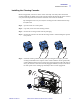
Installation Installation Procedure Attaching the Ribbon Take-Up Spool Step 1. Attach the Ribbon Take-Up Spool by sliding it onto the Ribbon Take-Up Spindle and pressing it straight back until in clicks into place. Important • Make sure that the Ribbon Take-Up Spool is attached with its “toothed” end toward the rear of the printer. The two figures below show the right and wrong ways to insert the printing ribbon on either spindle. Right way: the clip is OVER the core.
Installation Installation Procedure Installing the Ribbon i Series Printers require the use of i Series ribbons for full color printing. These Resin Thermal Transfer and Dye Sublimation ribbons are specifically designed for the i Series Printers. Note • In normal printer operation, when the ribbon is exhausted, a warning message appears on the monitor and the MEDIA indicator on the printer lights. Step 1. Open the printer Main Cover. The printhead will raise for easy ribbon loading. Step 2.
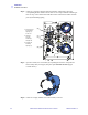
Installation Installation Procedure Step 5. Route the Ribbon as shown in the figure below. The Ribbon Supply Spindle is freewheeling; pull ribbon off it as needed. If the tape removed from the new ribbon in step 3 is undamaged, use it to attach the end of the ribbon to the Take-Up Spool; otherwise use other adhesive-backed tape.
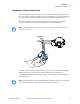
Installation Installation Procedure Installing the Cleaning Cassette Before being printed, each surface of the card is cleaned by a soft tacky roller that is itself cleaned periodically by adhesive tape in the Cleaning Cassette. By default, the roller is cleaned every 10 cards. The printer driver software allows the card count to be modified. By cleaning the roller every 10 cards, the Cleaning Cassette contains sufficient tape for 3,000 cards. Step 1. Open the main cover of the printer. Step 2.
Installation Installation Procedure Loading the Laminate Note • In this description of loading laminate, references to the lower Laminate Cassette apply only to the P640i Printer. The P640i Printer can apply laminate to both surfaces of the card; the P630i Printer only to the upper surface. The Laminate (laminating film) is loaded into cassettes to protect it from dirt or other contaminants. See the figure below.
Installation Installation Procedure Removing the Laminate Cassette(s) Step 1. The Laminate Cassette(s) (Upper only for the P630i Printer; Upper and Lower for the P640i) are held in position by latch plates. The Upper Cassette is freed by turning its Latch Plate counter-clockwise to a full vertical position; the Lower Cassette (only present on the P640i Printer) is freed by turning its Latch Plate clockwise. Then pull the cassette straight out from its holder.
Installation Installation Procedure Step 2. If there is a suspicion a patch is blocked somewhere, temporarily remove the corresponding Transfer Guide to be sure there are no scraps of laminate remaining. If there are any, remove them. Then slide the Transfer Guide back in until it is held in place by the Retaining Spring. 1. Push and hold the Retaining Springs (A) to the Left (B) 2. Slide the Transfer Guides (B) Straight Out (A) (A) 3. Release the Retaining Springs (A) (B) Step 3.
Installation Installation Procedure Loading the Laminate Cassette(s) Important • If you are using partial-width laminate in the Lower Cassette of a P640i Printer, read the following section, Using Partial-Width Laminate, before proceeding with this procedure. (Partial-width laminates are frequently used on the bottom surface of cards that have a signature panel or a magnetic stripe.
Installation Installation Procedure Step 3. Pull out an inch or two of laminate past the lip of the cassette. Step 4. Close the cassette by firmly pressing the “clamshell” together. You will hear a click and feel a detent when the halves of the cassette seat together. Step 5. Pull out a little more laminate between the lips of the cassette. If it suddenly stops, resisting further pulling, a spring detent on the cassette has probably snagged a notch on the end of the core.
Installation Installation Procedure Laminating Contact Smart Cards The laminating patch on the top surface of a smart card has a rectangular aperture to expose the card’s electrical contacts. In all other respects the laminating process for smart cards is the same as for ordinary cards. Note that this procedure also applies to registered laminates. The special laminate for the top cassette is punched with a repeated pattern.
Installation Installation Procedure Using Partial-Width Laminate Note • Since partial-width laminates are only used for the back (i.e., lower) surface of the card, this section only applies to the P640i Printer. Laminate come in three widths: “Full-Width” laminate is 2 in (51 mm) wide. Full-width laminate is used on the front (i.e., upper) or back (i.e., lower) surface of the card. “Partial-Width” laminate is available in two widths: • 1.