
User's Manual
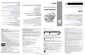

Dimension tolerance = ± 0.01 inch (± 0.25 mm)
2.26"
[57.28mm]
1.13"
[28.64mm]
5.05"
[128.27mm]
Introduction
The FLB3678 cordless scanner cradle acts as charger and radio communication
interface for the XX3678 cordless scanner. It attaches to a mounting bracket using three
isolators. The bracket is then mounted on the forklift surface.
The FLB3678 cradle receives data from the scanner via a Bluetooth radio, and sends
that data to the host through an attached cable. The cradle also charges the scanner’s
internal battery pack when the scanner is inserted. A portable power supply on the
forklift supplies power to the cradle.
This document provides basic instructions on setting up and using the cradle. Any
discussion of transmission of information refers specifically to the FLB3678 cradle.
CAUTION LS3578 and DS3578 cordless scanners are incompatible with
FLB3678 cradles.
Equipment Supplied
The cradle package includes:
•Cradle
• Mounting bracket with isolators
• Three 8-32 x 1.5” Phillips head screws (for attaching cradle to mounting
bracket).
Accessories
The following equipment may be needed:
• Three 1/4-20 screws, minimum length 1.0” (for fastening bracket to mounting
surface).
Save the shipping container for storing or shipping. Inspect all equipment for damage. If
anything is damaged or missing, call an authorized Zebra Support Center immediately.
Related Documentation
LI3678 Product Reference Guide, p/n MN001740Axx.
LI3678 Quick Start Guide, p/n MN002323Axx.
STB3678 Quick Reference Guide, p/n MN002334Axx.
This documentation is available at: www.zebra.com/support.
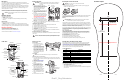
Cradle Parts
Charging/
Communications
Contacts
Pairing
Bar Code
Mounting
Screw Hole
Foot Latch
LED
Mounting
Screw Hole
PAIR
Drain Hole
Canopy Latch
Mounting
Screw Hole
Page Button
Drain Hole
Rubber Feet
Host Cable Latch
Host Cable (Under Latch)
Rubber Feet
Host Cable
Guide
Foot Latch
Release
Mounting
Screw Hole
Mounting
Screw Hole
Top View
Bottom View
Cradle Connections
1. Connect the appropriate cable to the
power supply and an AC power source, if
necessary. This will ensure detection of the
host and prevent inadvertently
back
p
owering the cradle from improper
detection of the host.
2. Insert the interface cable into the host port.
3. Lift the latch and connect the interface
cable into the cradle’s host port, then close
the latch.
4. If applicable, thread the host cable over
the cable hook and run the host and power
cables into their respective cable grooves,
or use cable ties to secure them to the
mounting plate after it is attached to the
cradle (see Mounting the Cradle).
5. Pair the scanner to the cradle either by
inserting it in the cradle (if Pair on Contacts
is enabled) or by scanning the pairing bar
code.
6. If necessary, scan the appropriate host bar code (for non-autodetected interfaces).
Refer to the Product Reference Guide.
Changing the Host Interface
To connect to a different host, or to the same host through a different cable:
1. Unplug the interface cable from the host.
2. Unplug the power supply from the cradle.
3. Connect the interface cable to the new host, or the new interface cable to the
existing host.
4. Reconnect the power supply, if required.
5. If necessary, scan the appropriate host bar code (for non-autodetected interfaces).
Refer to the Product Reference Guide.
Using a Host Interface to Supply Power
Some hosts can provide power to the cradle via the host interface, instead of an external
power supply.
IMPORTANT Connect the interface cable and power supply (if necessary) in
the following order to ensure proper operation of the scanner
and cradle.
CAUTION Always disconnect the DC power supply BEFORE disconnecting the
cable to the host end or the cradle may not recognize the new host.
Latch
Host Port
(Under Latch)
Mounting the Cradle
Horizontal Mount
1. Ensure the desk/wall mount
converter knob is in the correct
position, shown at right.
2. If mounting the cradle horizontally
where no fastening is necessary
,
peel
the protective paper from the
back of the rubber feet includ
ed
with
the cradle packaging, a
nd
attach the feet to the cradle at the
indentations in the plastic. These
feet provide traction and prevent
surface damage
.
Vertical Mount
To mount the cradle on a vertical surface:
1. Use a Philips screwdriver to turn the desk/wall mount converter knob to the position
shown below. The front latches protract to engage the depressions at the base of the
scanner’s handle.
2. Attach the interface and power
cables (see Cradle Connections).
3. Press the cables into the cable
groo
ves.
4. Position the cradle on the
mounting surface, or use the
template included in this guide.
5. Mark the surface through the
three holes on the bottom of the
cradle, or use the mounting
template to determine the location
of the screw holes.
6. Pre-drill holes to accommodate
th
ree 1.5" #8 Philips head screws.
7. Attach the cradle securely to the
surface.
8. Place the scanner in the cradle.
NOTE Do not use the rubber feet when mounting in a vertical orientation.
Converter Knob
Horizontal Position
Converter Knob
Vertical Position
Inserting the Scanner in the Cradle
To insert the scanner in the cradle:
• Insert the scanner top first. Push the handle until it clicks into place, engaging the
contacts in the cradle and scanner.
Sending Data to the Host Computer
The cradle receives data from the scanner via a wireless radio connection and transmits it
to the host computer via the host cable. The scanner and cradle must be paired for
successful wireless communication.
Pairing
Pairing registers a scanner to the cradle such that the scanner and cradle can exchange
information. The FLB3678 operates in two modes: Point-to-Point and Multipoint-to-Point. In
Point-to-Point mode, pair the linear imager scanner to the cradle either by inserting it in the
cradle (if pair on contacts is enabled), or by scanning the pairing bar code. In Multipoint-to-
Point mode, you can pair up to seven scanners to one cradle.
To pair the linear imager scanner with the cradle, scan a pairing bar code. A high-low-high-
low beep sequence followed by a low-high beep sequence indicates successful pairing and
connection to the remote device. A long low, long high beep sequence indicates
unsuccessful pairing.
Lost Connection to Host
If scanned data does not transmit to the cradle’s host, ensure that all cables are firmly
inserted and the power supply is connected to an appropriate AC outlet, if applicable. If
scanned data still does not transmit to the host, reestablish a connection with the host:
1. Disconnect the power supply from the cradle.
2. Disconnect the host interface cable from the cradle.
3. Wait three seconds.
4. Reconnect the host interface cable to the cradle.
5. Reconnect the power supply to the cradle, if required.
6. Reestablish pairing with the cradle by scanning the pairing bar code.
CAUTION Do not pour, spray, or spill any liquid on the cradle.
NOTE The pairing bar code that connects the scanner to a cradle is unique to
each cradle.
Do not scan data or parameters until pairing completes.
Charging the Scanner Battery in the Cradle
When using a new battery in the scanner, the battery requires a charge to be enabled.
Insert the battery in the scanner and place the scanner in the FLB3678 cradle (see
Inserting the Scanner in the Cradle). The battery begins charging when the scanner LED
indicator starts flashing amber. The battery is fully charged when the cradle LED is solid
green. A complete charge of a fully discharged battery can take up to three hours using
external power and up to ten hours using the USB interface cable.
Cradle LED Indicators
Troubleshooting
If the cradle does not work after following the previous procedures:
• Check the system power.
• Check for loose cable connections.
• Check that the scanner is inserted properly in the cradle.
• Check that the host settings are correct and the cradle is connected to the appropriate
port on the host.
LED
Indication
Green Power on
Green flashing Bluetooth connection established
Blue Page button
Amber (fast fast slow) Scanner page issued
Battery Indications
Amber Blinking Charging
Amber fast blinking Charging error
Green
Fully
charged
Wall Mount Template
Pending Template Replacement
Pending Template Replacement
Draft 1_Reg Submission