ZebraStat ® Model ZS-2 Operation Manual
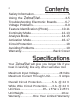
Contents Safety Information........................................3 Using the ZebraStat.............................4-5 Troubleshooting Electronic Boards..........6-7 Voltage Problems......................................8-9 Feature Identification (Photo)................10-11 Continuity Mode....................................12-13 Analysis Mode.......................................14-15 Activation Mode....................................16-17 Circuit Protection........................................
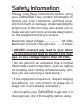
Safety Information 3 Please read these instructions before using your ZebraStat.They contain information to protect you, your customers, and their property from harm or damage. Understanding the proper use of this tool may also assist you to make quicker and more accurate diagnostics on the equipment that you service. Maximum Input Voltage.....................28 Volts Maximum Current Through Unit.........
Using the ZebraStat To use your ZebraStat, follow these steps: 1) Decide the mode that you want to use 2) Hook up appropriate leads to equipment 3) Manipulate Mode & Component switches 4) Observe the LED’s and equipment tested Explanation of steps: 1) Mode. ZebraStat operates in 3 different modes. You can easily leave it hooked up and use all 3 modes on the same equipment as needed. The 3 modes are: • Continuity - This mode tests that the wires that you connect to electrically ‘go somewhere’.
Using your ZebraStat (continued) 5 • Activate - This mode is like having a remotecontrol thermostat. Technicians often use it when the thermostat is not easily accessible: when making a diagnosis or repair to a unit in an attic, basement, roof, or new construction where the thermostat hasn't been installed yet. 2) Hook-Up. Start with the Mode Switch in the ANALYZE position and have all component switches OFF. The hookup of Zebra-Stat’s leads is the same for all modes.
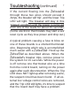
Troubleshooting Electronic Boards A blown fuse on an electronic control board presents special challenges. Rather than just replacing the fuse (and possibly watch it ‘blow’ again) the ZebraStat offers a diagnostic alternative. The White wire (the HEAT1 circuit) has a special function built into it. Between the Red and White wires is a low-amp, autoreset, solid-state 'circuit breaker'.
Troubleshooting (continued) 7 If the current flowing into the Zebrastat through these two wires should exceed 3 Amps, the breaker will ‘trip’, and the lower Trip LED will light. The breaker will stay in this ‘tripped’ condition until the power is removed from one of the leads for about 15 seconds. (Some electronic thermostats may start a set/ reset cycle as they lose power and drop out.) A typical problem causing a fuse to blow on one of these boards is a shorted thermostat wire.
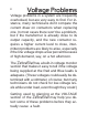
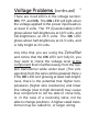
Voltage Problems Voltage problems in a system are frequently overlooked, but are very easy to find. For instance, many technicians don’t compare the current draw on contactors when replacing one. In most cases there won’t be a problem, but if the transformer is already close to its output capacity, and the new contactor requires a higher current level to close, intermittent problems are likely to arise, especially if the line voltage drops a few percent because of high demand, say, on a hot afternoon.
Voltage Problems (continued) 9 There are 3 red LED’s in the voltage section: ON, ??, and OK. The ON LED will light when the voltage applied to the power input leads is at least 8 volts. The ?? (Questionable) LED glows about half-brightness at 19.5 volts, and full-brightness at 20.5 volts. The OK LED glows about half-brightness at 21.5 volts, and is fully bright at 23 volts.
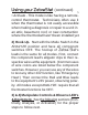
Feature Identification Mode Switch Upper Trip LED (Red) Voltage Monitor Lower Trip LED Lead Compartment Magnet (on back) Quick Reference ZebraStat Model ZS-2
on -2 11 Hanging Hook Component Switches Component Displays Continuity LED’s (6 - Green) Activation LED’s (6 - Yellow) Wire Color Codes Leads Velcro Strap
Continuity Mode Continuity Mode tests that the wires your ZebraStat’s leads are connected to ‘go somewhere’ electrically. For instance, the wire that you connected the FAN lead to normally goes through a fan relay. Using this mode will tell you if there is a continuous circuit through that relay on the other end of the wire. 1) Turn all thermostat functions to OFF. 2) Turn all the ZebraStat ’s component switches to OFF, and put the Mode Switch in the ANALYZE position.
Continuity (continued) 13 Caution: The continuity mode passes a very small amount of current to ‘test’ each of the circuits that it is connected to. As more modern equipment uses computer-type processing boards to control equipment, some may be designed that have functions that might be activated by the ZebraStat’s tiny (about 7 milliamps) of current to test the different circuits. Be aware that some circuits might possibly be activated while testing in Continuity Mode.
Analysis Mode Analyzis Mode simply displays any control power that is being sent to the circuits that your leads are connected to. The red LED’s will indicate the level of AC power available at the equipment. Yellow component LED’s will illuminate on each circuit that is currently energized. This mode is often used by a tech to isolate the general area of a problem. For instance, you turned the FAN switch on at the thermostat, but the fan does not start.
Analysis (continued) 15 2) Attach the ZebraStat’s component lead’s alligator clips to the appropriate equipment wires, then attach the Red and Blue power leads to the equipment’s 24VAC hot and common wires, observing polarity. 3) Notice which yellow LED’s are illuminated under their component switches. (All of the component switches must be OFF.) These LED’s indicate which circuits are currently receiving power.
Activation Mode Activation mode is similair to having a remotecontrolled thermostat. Technicians often use this mode when the thermostat is not easily accessible, as in when making a diagnosis or repair to equipment in an attic, basement, on a roof, or other location remote from the area where the thermostat is located. 1) Turn all thermostat functions to OFF. 2) Turn all of the ZebraStat’s component switches to OFF, and put the Mode Switch in the ANALYZE position.
Activation (continued) 17 Caution: Remote activation can surprise another technician working elsewhere on related equipment. Communicate your intentions to anyone else involved. For instance, when remotely activating the cooling stages of a system; you don’t want to start a fan or compressor that someone may be inspecting. 5) Turn the Mode Switch to ACTIVATE. 6) Turn on component switches as appropriate.
Circuit Protection Your ZebraStat provides circuit protection in two ways. Each uses a solid-state, automatically-resetting circuit breaker device. The white test lead is protected with a 3 Amp device. You can learn more about its use in the “Troubleshooting Electronic Boards” section. The second device provides an overall protection for the ZebraStat. It is rated at approximately 5 Amps at 28 Volts.
Avoiding Problems 19 1) The “power-in” wires (RED & BLUE) ARE POLARIZED, even though it’s an AC circuit! The RED lead must connect to the equipment’s HOT wire (usually red), and the BLUE lead must connect to the equipment’s COMMON wire (usually brown or blue). REVERSING THESE LEADS CAN CAUSE THE ZebraStat’s CIRCUIT BREAKER TO TRIP. 2) If you are getting a strange LED indication in either the CONTINUITY or ANALYZE modes, it could be caused by having one of the ZebraStat’s component switches ON.
One Year Limited Warranty For a period of one (1) year from the original end-user’s date of purchase, Zebra Instruments warrants that this tool will perform as described. Should you encounter any problems, please contact us and we will attempt to resolve your problem as quickly as possible. This resolution may include replacement; exchange; or repair of a defective unit, at our option.