
Install Instructions
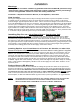
Table Of Contents

Installation
Warnings:
• This product should be installed by qualified and trained HVAC/R personnel only!
• Disconnect supply voltage and discharge system capacitors before proceeding!
• Follow all applicable electrical codes and safety standards!
Contents: 1 Zap-Pro Protection Device; 4 Tab Splitters; Twist Ties
How it works:
As long as voltages remain normal, Zap-Pro simply allows them to pass unimpeded. However,
if voltage swings (or spikes) too high, the three devices in Zap-Pro act to clamp or clip off the
excess voltage. Typical response time is 28ns - 30ms. The excess voltage is converted to heat en-
ergy and dissipated as long as it isn’t excessive. These protectors can dissipate up to about 8000v
for one cycle, or 4000v for 2 cycles, etc., before being damaged (often with an audible ‘pop’) and
shorting their poles together permanently, which will cause the circuit breaker to trip. This dam-
aged condition is usually visible inside the clear shrink wrapping as a discoloration and the circuit
breaker will continue to trip when power is restored. REPLACE the Zap-Pro - don’t just disconnect
it - it has done its job protecting the unit’s (or circuit board’s) components.
Installing Zap-Pro on a Heat Pump Unit or Condensing Unit:
Disconnect all power to system.
Locate the LINE side of contactor. Install Zap-Pro’s Black
and Red wires to the 1/4” Male tabs on the side of contactor that is always ‘hot’. This is done
because many systems have transformers or other devices that are always ‘on’, and connecting
the Zap-Pro to this side protects all parts full time, not just when the contactor is energized. Route
the green/yellow wire to a place where it can be permanently attached to a good ground point, and
secure tightly. Use provided twist ties to insure wires do not rub on sharp edges during vibration,
and away from rotating parts. Peel off and apply “Tech Note” sticker.
Installing Zap-Pro on a Circuit Board in a Furnace, Air Handler, or other Unit:
to the board. Some boards will have an extra connector for each leg to be connected to, but it is
BEST if you use the 2-to-1 connectors provided, attaching them directly to the incoming power
terminals. Use the Zap-Pro’s Black wire to attach to the Black or ‘hot’ incoming wire, and use
the Zap-Pro’s Red wire to attach to the Neutral side (or the other power leg if the board receives
240v power.) The green/yellow ground wire must be securely attached to the best ground point
available. Tighten the screw securely. Tie off any wires that might be exposed to sharp or rotating
parts, or that might be damaged by vibration. Peel off and apply the “Tech Note” sticker in a con-
spicuous place.
Red and Green LED Monitors:
The Red and Green Monitor LED’s indicate the voltage and protection status of the power line
that they correspond to: The Green LED is for the Black Power Lead, and the Red LED is for the
RED Power Lead. IF the RED Power Lead is connected to the equipment’s Neutral terminal
(as would be the case if the unit operates only on 120V) THE RED LED WILL NEVER LIGHT.
That is normal, because each LED only monitors the status if it is at LINE potential. Other than
that exception, a dark LED indicates either a) power loss, b) loss of protection, or c) ground loss.
Notes: • A normal Zap-Pro device measures near ‘infinity’ Ohms across any two leads.
• A failed device will measure low resistance between some of the leads.
• Also use Zebra HVAC’s ECM Motor Protectors; Models VZPRO and
Disconnect all power to System. Locate the tab connectors where incoming power is supplied
Circuit Board
Protection
Condensing Unit
Protection
Contactor
l
Terminals
l