
User Guide
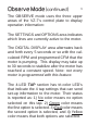
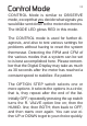
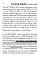
Table Of Contents

12
Control Mode (continued)
The SETTING STEP switch operates in the
same way, but it’s choices are: OFF - h1 - h2
- c1 - c2 - FA - H1 - H2 - C1 - C2 - OFF. Select-
ing the capital letter for H or C will simulta-
neously make the FAN line active. Alternately,
stopping on a choice that has a small h or c
will send signals only down those lines; the
FAN line will NOT be activated. The 1 or 2 af-
ter the Heat or Cool means which stage, when
using a multi-stage unit. There is a delay of a
few seconds after you stop on your choice,
before the lines switch to that choice.
In the CONTROL mode, you will notice that
only the middle set of 7 LED’s change. The
left-hand set keep displaying what the sys-
tem is calling for.
This allows you to effectively
isolate the rest of the system from the motor
(assuming the connected line voltage is cor-
rect) and positively prove which component
is having problems. If you conclude that the
motor is defective, go on to the WINDING
TEST to identify which section to replace.