Variable Speed Zebra Model VZ-7 Operation Manual
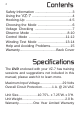
Contents Safety Information .......................................3 Using the VZ-7 ..........................................4 Hooking-Up ...........................................4-5 Choosing the Mode ....................................6 Voltage Checking .......................................7 Observe Mode ......................................8-10 Control Mode ......................................11-12 Winding Test Mode ............................13-14 Help and Avoiding Problems.................
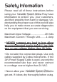
Safety Information 3 Please read all of these instructions before using your Variable Speed Zebra.They have information to protect you, your customers, and their property from harm or damage. Understanding the proper use of this tool will also help you to make more accurate diagnostics on the equipment that you are servicing. Maximum Input Voltage.....................29 Volts Maximum Current Through Unit.........
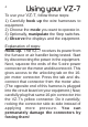
Using your VZ-7 To use your VZ-7, follow these steps: 1) Carefully hook up the wire harnesses to equipment. 2) Choose the mode you want to operate in. 3) Optionally, manipulate the Step switches. 4) Observe the displays and the equipment. Explanation of steps: Hook-Up. The VZ-7 receives its power from the furnace or air handler being tested. Start by disconnecting the power in the equipment. Next, squeeze the ends of the 5-wire power connector on the motor and disconnect it.
Hook-Up (continued) 5 The VZ-7’s blue connector should be carefully plugged into the motor’s 16-pin receptacle. Finally, re-insert the 5 pin power connector into the motor’s socket. (Because of the power surge to charge the motor’s capacitors, NEVER plug in the power connector when voltage is on!) The VZ-7’s white harness isn’t connected at this time. Power up. . Note: A small number of furnace or air handler manufacturers choose not to run a 24V hot wire in their harnesses to the motor.
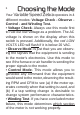
Choosing the Mode Your Variable Speed Zebra operates in 4 different modes: Voltage Check - Observe Control - and Winding Test. • Voltage Check- Always use this mode first to rule out low voltage as a problem. The AC voltage is shown on the display when this switch is pressed. Additionally, the red LOW VOLTS LED will flash if it is below 20 VAC. • Observe Mode- is just that: you are observing the signals that the equipment is sending to the motor’s electronics.
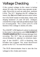
Voltage Checking 7 If the control voltage to the motor is below about 20 volts, the motor may operate erratically. Since this is such an easy test, perform it first. The VZ-7 displays the AC voltage between the Hot and Com harness wires when the VOLTAGE switch is held down. Most units display between 21 and 29 VAC. Voltages outside this range indicate problems that must be investigated. The LOW VOLTS LED flashes if the voltage is below 20 volts.
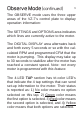
Observe Mode OBSERVE mode (Green MODE LED) is meant for you to use when you’re diagnosing if the equipment is sending the proper signals to the motor. It is sometimes confusing because a few manufacturers do not follow the suggested uses of the signal lines. For instance, one manufacturer sends a signal to the motor down the FAN line when they want the motor to operate at heat speed.
Observe Mode (continued) 9 The OBSERVE mode uses the three upper areas of the VZ-7’s control plate to display operation information: The SETTINGS and OPTIONS area indicates which lines are currently active to the motor. The DIGITAL DISPLAY area alternates back and forth every 5 seconds or so with the calculated RPM and programmed CFM that the motor is pumping. This display may take up to 30 seconds to stabilize after the motor has reached a constant speed.
Observe Mode (continued) Usually these tap settings are set with DIP switches or removable shunts. They control the ramp-up and ramp-down speeds, start delays and stop delays, and sometimes, allowing you to set up a unit to run slightly faster or slower; to the customer’s preference. We display the settings here so you can spot something that is set incorrectly. Remember that you must remove, then reapply, power to the motor before the new settings are active.
Control Mode 11 CONTROL Mode is similar to OBSERVE mode, except that you decide what signals you would like sent down to the motor electronics. The MODE LED glows RED in this mode. The CONTROL mode is used for further diagnosis, and also to test various settings for problems without having to reset the system thermostat. Detecting the RPM and CFM of the various modes that a system can be set to is best accomplished here.
Control Mode (continued) The SETTING STEP switch operates in the same way, but it’s choices are: OFF - h1 - h2 - c1 - c2 - FA - H1 - H2 - C1 - C2 - OFF. Selecting the capital letter for H or C will simultaneously make the FAN line active. Alternately, stopping on a choice that has a small h or c will send signals only down those lines; the FAN line will NOT be activated. The 1 or 2 after the Heat or Cool means which stage, when using a multi-stage unit.
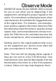
Winding Test Mode 13 The WINDING TEST Mode is performed on a motor that is already shown to be defective. It’s used to identify if the windings section of the motor is defective also, or if you only need to replace the electronics module on the end of the motor. Since the complete motor costs hundreds of dollars, and the electronics package can be about $100, it makes good sense to replace just the pack if possible. • Hook-Up: Shut off power. Disconnect the Line Power plug at the motor.
Winding Test Mode (continued) Now, press and release the WINDING TEST switch; the display makes a circular pattern to remind you that the motor shaft needs to be turned one or two revolutions to test it. The digital display gives the results of the test: “00” means connector is not connected.
Avoiding Problems & Help 15 Don’t disassemble the VZ-7. IC’s inside are sensitive to static charges that might occur if they are touched. Warranty will be void. Be very gentle when connecting cables; the pins can easily be damaged. Never force connectors together, gently wiggle them. If the VZ-7’s cable harnesses get damaged, replacement harnesses are available; follow the instructions carefully to avoid static discharge.
One Year Limited Warranty For a period of one year from the original end-user’s date of purchase, Zebra Instruments warrants that this tool is without manufacturing defects. Should you encounter any problems, please contact us and we will attempt to resolve your problem as quickly as possible. This resolution may include replacement, exchange, or repair of a defective tool; at our option.