
Data Sheet
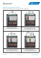
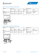


Application wiring diagrams (examples)
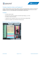
Raspberry Pi pins and M5S pins need to be connected by jumpers or jumper cables.
JP_0V
-
+
JP_V+
3
V
3
5
V
G
V
S
S
V
G
MIO-8-RaserryPi(V2.0)
For Raspberry Pi
WWW.ZDAUTO.COM
I/O
Power
26
28
27
29
32
31
33
35
36
37
38
40
19
18
15
13
16
11
12
10
7
8
5
3
21
22
M5S SmartRelay
3.3V
3 5
GND 11 13 15 3.3V 19 21 23 GND 27 29 31 33 35 37 GND
5V 5V
GND
8 10 12 16 18 22 24 26 28 GND 32 GND 38 40GND
GND
7
36
24
23
1
→
8
M5S-BID0324B1
24 V
U
+ −
JP_0V
-
+
JP_V+
3
V
3
5
V
G
V
S
S
V
G
MIO-8-RaserryPi(V2.0)
For Raspberry Pi
WWW.ZDAUTO.COM
I/O
Power
26
28
27
29
32
31
33
35
36
37
38
40
19
18
15
13
16
11
12
10
7
8
5
3
21
22
M5S SmartRelay
3.3V
3 5
GND 11 13 15 3.3V 19 21 23 GND 27 29 31 33 35 37 GND
5V 5V
GND
8 10 12 16 18 22 24 26 28 GND 32 GND 38 40GND
GND
7
36
24
23
1
→
8
M5S-BO T 03750D1b
24 V
U
+ −
Detecting a voltage of 24 V DC.
Input wiring diagram BID0324B1.
M5S 1 connected to Raspberry Pi pin 16 (GPIO23).
Switching of a load with a maximum voltage of 24 V DC
and a maximum current of 750 mA.
Output wiring diagram BOT03750D1b.
M5S 2 connected to Raspberry Pi pin 11 (GPIO17).
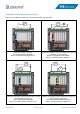
JP_0V
-
+
JP_V+
3
V
3
5
V
G
V
S
S
V
G
MIO-8-RaserryPi(V2.0)
For Raspberry Pi
WWW.ZDAUTO.COM
I/O
Power
26
28
27
29
32
31
33
35
36
37
38
40
19
18
15
13
16
11
12
10
7
8
5
3
21
22
M5S SmartRelay
3.3V
3 5
GND 11 13 15 3.3V 19 21 23 GND 27 29 31 33 35 37 GND
5V 5V
GND
8 10 12 16 18 22 24 26 28 GND 32 GND 38 40GND
GND
7
36
24
23
1
→
8
M5S-BO T03750D1b
24 V
U
+ −
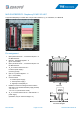
JP_0V
-
+
JP_V+
3
V
3
5
V
G
V
S
S
V
G
MIO-8-RaserryPi(V2.0)
For Raspberry Pi
WWW.ZDAUTO.COM
I/O
Power
26
28
27
29
32
31
33
35
36
37
38
40
19
18
15
13
16
11
12
10
7
8
5
3
21
22
M5S SmartRelay
3.3V
3 5
GND 11 13 15 3.3V 19 21 23 GND 27 29 31 33 35 37 GND
5V 5V
GND
8 10 12 16 18 22 24 26 28 GND 32 GND 38 40GND
GND
7
36
24
23
1
→
8
M5S-AOA03020D3Ab
24 V
U
+ −
A
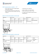
Switching of a load with a maximum voltage of 24 V DC
and a maximum current of 750 mA.
Output wiring diagram BOT03750D1b.
M5S 2 connected to Raspberry Pi pin 12 (GPIO18).
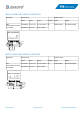
Output of an analogue current ranging from 0 to 20 mA
with voltage supply 24 V DC.
Output wiring diagram AOA03020D3Ab.
M5S 4 connected to Raspberry Pi pin 10 (GPIO15).
Rev-2019-08 Page 15 of 20 www.tde-instruments.de