
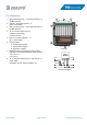
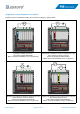
Data Sheet
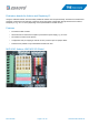
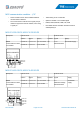


Pin assignment
1: (EXT+) External circuit +, connected to all pins 7 of
the M5S modules
2: (EXT-S-1..8) External signals 1 - 8
(pin 8 of each M5S)
3: (EXT−) External circuit -, connected to all pins 6 of
the M5S modules
4: JP_0V connects external circuit −
to internal power supply −
(common ground)
5: (INT-S-1..8) Internal signals 1 - 8
(pin 1 of each M5S)
6: Connector field
G: Internal power supply -
V: Internal power supply +
S: Signal pin of Arduino
7: POWER connects the voltage rail of the Arduino
with all pins 3 of the M5S modules (supply of M5S):
- Pin 1-2: 3.3 V
- Pin 2-3: 5 V
8: JP_V+ connects external circuit + with internal 5 V
power supply.
(CAUTION, only for external voltage 5 V!)
Rev-2019-08 Page 12 of 20 www.tde-instruments.de
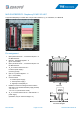
M5S
EXT+
EXT−
EXT-S
5V
3.3V
INT-S
INT−
JP_V+
JP_0V
1 2 3 4 5 6 7 8
POWER
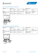
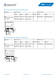
Connection diagram
Overview
3
.
3
V
5
V
G
N
D
G
N
D
V
i
n
A
0
A
1
A
2
A
3
A
4
A
5
7
6
5
4
3
2
1
0
1
4
1
3
1
2
1
1
1
0
9
8
G
N
D
J
P
_
0
V
-
+
J
P
_
V
+
3
V
3
5
V
G
V
S
S
V
G
A
r
d
u
i
n
o
U
N
O
&
L
e
o
n
a
r
d
o
M
I
O
8
-
A
r
d
u
i
n
o
(
V
2
.
0
)
M
5
S
S
m
a
r
t
R
e
l
a
y
WWW.ZDAUTO.COM
I
/
O
0
1
2
3
4
5
6
7
8
9
A
0
A
1
A
2
A
3
A
4
A
5
1
3
1
2
1
1
1
0
1
→
8
P
o
w
e
r
2 31
4
6
7
8
5