
User guide

zBOOST® METRO YX540 USER GUIDE
7
zBOOST® METRO YX540 USER GUIDE
8
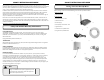
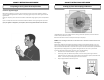
When your zBoost® system is in place and fully connected, you should walk throughout the room and see
that you are able to reliably place calls.
Remember, coverage varies based on outdoor signal level, building construc on, and antenna placement.
Coverage in adjoining rooms (next to, above, or below) will be reduced due to walls or ceiling/fl oors.
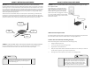
Should you desire to improve coverage, you may:
• Move the Base Unit and/or adjust the angle of the Base Unit Antenna.
• Move the antenna around the window – higher is usually be er.
• Move the Base Unit farther from the Signal Antenna or around a wall.
Improving Your Coverage Area
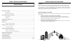
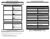
Solid GREEN Normal condi on at power up.
Slowly Alterna ng RED and GREEN zBoost® is working, but at reduced
performance and coverage due to “non-
ideal” setup.
Solu on: Increase the distance between
antenna and amplifi er to achieve
maximum performance and coverage.
Fast Flashing RED Indicates insuffi cient distance between
the antenna and the amplifi er. The
amplifi er is opera ng at signifi cantly
reduced coverage.
Solu on: Increase space between base
unit and antenna.
Solid RED System is receiving signals from either
the mobile device or the base sta on
transceiver which are too strong for
proper opera on.
Solu ons: Move away from receiving
antenna with your cell phone. Move
antenna away from other devices..
Fast Alterna ng RED and GREEN followed
by no light
The amplifi er is disabled.
Solu on: Unplug and start over.
At Initial Power Up Only
zBoost® Base Unit Light Indicators
After Initial Power Up
Solid GREEN Normal condi on.
Solid RED System is receiving signals from either
the mobile device or the base sta on
transceiver which are too strong for
proper opera on.
Solu on: Please unplug your system. Re-
orient your Signal Antenna and/or Base
Unit to reduce the excessive signal source.
Plug your system back in. If s ll solid red,
call customer support 1-800-871-1612..
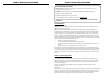
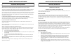
Product Speci cations for zBoost METRO – YX540 – Dual Band
PCS band
Frequency Uplink: 1850 to 1910 MHz
Downlink: 1930 to 1990 MHz
System Gain 54dB
PCS bands supported A, D, B, E, F, C
Networks CDMA, GSM, GPRS, EDGE, EVDO, 1xRTT,
UMTS, HSPA, 3G
Cellular band
Frequency Uplink: 824 to 849 MHz
Downlink: 869 to 894 MHz
System Gain 52dB
CEL bands supported A, B, A’, B’
Networks CDMA, GSM, GPRS, EDGE, EVDO, 1xRTT,
UMTS, HSPA, 3G
General
Power Consump on – Power Supply Current 3W standby; 7W max signal - 2.0A Max
Wall Supply Input ; Voltage 100-240VAC 50-60 Hz ; 5.0VDC
System Cer fi ca ons FCC Parts 15 & 24 (PCS) and Parts 15 & 22
(CEL), Industry Canada
Base Unit Size and Weight 5” x 7” x 1.25” – 9 oz.
Opera ng Condi ons Indoor Use Only (40- 105 F)
Coverage (open areas) Over 1500 sq
This product uses patented technology to protect the carrier network
This product is covered by patent US 7,706,744. Other U.S.
and foreign patents pending.