
User Manual

zBoost
®
ZB645 Platinum Manual zBoost
®
ZB645 Platinum Manual
4 5
Power Requirements
The Base Unit can be plugged into a standard 2-prong 110 VAC receptacle using the included
power supply. The power supply consumes less than 10W (less than 0.2A).
Important Reminders:
An exterior mounting mast has not been provided. Using at least 1.5” PVC pipe or a J-pole
(available from zBoost, part YX014) is suggested should one be needed.
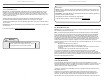
Coax Cable
Exterior Wall
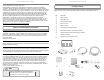
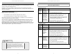
Before installing, please note the following important factors in determining your zBoost
performance:
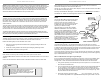
• At least 15 vertical feet is needed between the External Antennas (receives the outside signal)
and the Indoor Antenna (rebroadcasts the signal indoors). Separation less than 15 vertical
feet will result in decreased performance. See illustration below.
• Keep the External Antenna at least 3 feet above any metal.
See “Installing Your zBoost Signal Booster” on page 5, for additional information.
Cable Requirements
RG-6 cable is used to connect the External Antenna and the Base Unit. Should you need additional
cable length, 15 foot extensions (Part #: YX030-15w) are available at www.zBoost.com.
The total cable length should not exceed 65 feet unless you also purchase an upgraded External
Antenna or upgrade the cable to RG-11. (see page v). The recommended maximum length
for RG-11 is 120 ft. A longer cable is helpful only if it allows you to place the External Antennas
in a location where you measure stronger signal. It is highly recommended that you refrain from
securing your cable, drilling any holes, etc. until you complete and test the installation of the
system.
Caution: Before drilling any holes into a wall to run your cable, make sure you know where existing
electrical wiring is located. Drilling into live electrical wiring could cause an electrical shock and
sever the wire.
Grounding the Directional External Antennas
If you decide to place the External Antennas outdoors, it must be properly grounded. (See page
v for a recommended grounding kit).
The set up must be in accordance with Article 810 of the
National Electric Code (NEC). A listed antenna discharge
unit must be provided for the lead-in coaxial cable per NEC
article 8.10.20 or the shield of the coaxial cable must be
permanently and effectively grounded in accordance with
NEC article 8.10.21. Please consult a professional installer
or electrician for more information.
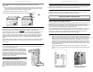
Securing Cable with a Drip Loop
When you install the Directional External Antennas, create
a drip loop with the coaxial cable at the point where the
cable enters the home through an outside wall. This can be
done by twisting and securing the cable into a loop (no less
than 4” across) near the entry point. This will help prevent
moisture from gathering at entry point and leaking into the
home.
15 ft of
Vertical
Separation
Maximum PerformanceMinimum Performance
Installing Your zBoost Signal Booster
FIRST: Placement of the External Antennas
Choosing the best location for the External Antennas provides the best performance and the largest
area of improved signal. Choose a location for the External Antennas using your cell phone to
determine the area of strongest signal - typically found outside, above the roofl ine or in an attic. The
antenna must also remain at least 3 feet from any metal objects such as pipes, metal siding, A/C
unit etc. and at least 15 vertical feet above the Indoor Panel Antenna.
The YX699 Signal Meter (available separately) provides signal strength information. It can be used
with its supplied whip antenna to fi nd the best location for antenna mounting with the strongest
received signal. It can also be connected to the directional antennas to aim the antennas for
maximum received signal. Contact zBoost to obtain a YX699 Signal Meter.
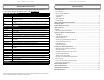
Mounting of Antenna
1. When you have determined the location of the strongest signal for both the PCS and CEL
frequencies, install the antennas to a mast (not provided). Outdoor J-pole Antenna Mounting
Bracket, YX014 is available at www.zBoost.com. Loosely connect the antenna to the mast
to allow the antenna to be reoriented for strongest signal. Take special care in aiming the
External Antennas in the direction of best signal. The External Panel Antenna works off the
PCS frequency and the Directional Yagi Antenna works off of the CEL frequency. If you are
unsure of the nearest tower location of your wireless provider, see”Antenna Aiming” on page
7 for detailed instructions.
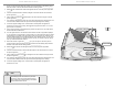
2. After installing the External Antenna to a mast or pole, connect each to the provided
Combiner then run a connection between the Combiner and Base Unit using the RG-6 coax
cable.
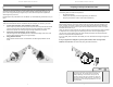
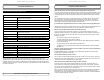
External Yagi Antenna
Bracket Assembly
External Panel Antenna
Bracket Assembly