
User Manual

zBoost
®
ZB545 Manual zBoost
®
ZB545 Manual
6 7
THIRD: Run the Coaxial Cable
NOTE: Refrain from securing cable or drilling
holes until the system has been tested.
Connect the supplied 35 feet of RG-6 coaxial
cable to the base of the External Antenna. Run
the coaxial cable along a descending pipe or
through a wall that leads closest to the location
of the Base Unit. Should you need additional
cable length, 15 foot extensions (Part #:
YX030-15w) are available at www.zBoost.com.
Please note: Cable longer than 65 feet is not
recommended.
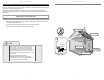
FOURTH: Connect zBoost Base Unit
to Power
Connect the zBoost Base Unit to the power
supply and plug into a power outlet. When your zBoost system is in place and fully connected, walk
throughout your home and verify that you are able to reliably place calls. If the signal strength has
improved, your zBoost is working.
Upon initial power up, the LED will cycle RED, GREEN and ORANGE for 30 seconds. After 30
seconds, a series of GREEN fl ashes will indicate the quality of your setup. Following this, a solid
GREEN light indicates normal conditions. If it is not solid GREEN, follow the instructions in the
Base Unit LED Indicators section. Adjustments may be needed to optimize performance. If you fi nd
the increased signal coverage is acceptable, however, no additional adjustments are needed. See
“zBoost Base Unit Light Indicators” on page 10) for more information.
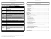
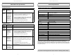
zBoost Base Unit
Power Supply
Indoor Antenna
Coaxial Cable
Wall Mounting
Bracket
Setting Up Your zBoost Signal Booster
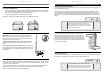
FIRST: Mount the External Antenna
Choosing the best location for the External Antenna provides
the best performance and the largest area of improved signal.
Choose a location for the External Antenna using your cell phone
to determine the area of strongest signal - typically found outside,
above the roofl ine or in an attic. The antenna must also remain
at least 3 feet from any metal objects such as pipes, metal
siding, A/C unit etc. and at lease 15 vertical feet above the Panel
Antenna.
Identify the best location for attachment of the mounting bracket
– such as an attic cross or main beam. Secure the mounting
bracket at the highest possible point.
Position the mounting bracket such that the External Antenna
will be vertical and attach the External Antenna. See “Antenna Bracket Assembly” below for more
information.
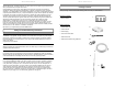
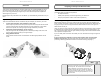
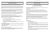
Antenna Bracket Assembly
IMPORTANT: Incorrectly mounting the External Antenna to the
mounting bracket (see fi gure A) will impede performance. Ensure
that the External Antenna is properly positioned in the mounting
bracket as pictured below.
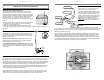
To mount External Antenna to a pole: Attach antenna to pole
bracket as pictured. Use U-Bolt to secure bracket to pole and
fasten. DO NOT mount to a metal pole.
To mount External Antenna to a fl at surface: Attach antenna to
pole bracket as pictured. Secure bracket to desired surface using
provided screws. Use of the Saddle and U-Bolt are not necessary
for this option.
SECOND: Place the zBoost Base Unit where you want to create a Cell Zone
TM
Connect the Indoor Antenna to the Base Unit and place it where you need signal. For the widest
possible signal area, position the Base Unit near the middle of a room. You may also mount it on an
interior wall by fi rst removing the bracket, screwing the bracket to a wall (screws not included), then
snapping the Base Unit back in place keeping the Indoor Antenna vertical. The Base Unit uses an
omni-directional Indoor Antenna that delivers signal in a circular pattern around the antenna.
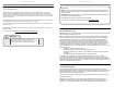
The zBoost requires at least 15 feet of vertical separation between the Base Unit and the External
Antenna. Generally, increasing this distance (up to 40 feet) will increase the performance and
decreasing the distance will limit the performance.
Keep the Base Unit off the fl oor and at least 2 feet away from other cords, metal objects or other
wireless devices such as wireless routers or wireless access points. The zBoost performs best
when there are no obstructions between the zBoost Base Unit and your mobile device.
15’ of vertical
separation
15’ of vertical
separation
15’ of vertical
separation
Figure A
Pole Bracket
Saddle
U-Bolt