
User Manual


zBoost
®
Xtreme ZB545X Manual
zBoost
®
Xtreme ZB545X Manual
6 7
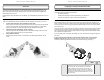
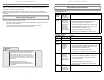
THIRD: Run the Coaxial Cable
NOTE: Refrain from securing cable or drilling holes until the system has been tested.
The zBoost Xtreme comes with 2 coax cables (35 ft. and 15 ft.) and a window-entry cable to
connect the External Antenna and the Base Unit. If you do not plan to run the cable through a
window, the window entry cable is not needed.
To run the coax cable through a window: Connect the two provided RG-6 cables (35 feet & 15
feet) using the provided window-entry cable. Use the attached cables to connect the Base Unit and
External Antenna through a window, positioning the window-entry cable at the window closing.
To run the coax cable through a wall: Connect the two provided RG-6 cables. Then connect one
end of the cable to the base of the External Antenna. Run the coaxial cable along a descending
pipe or through a wall that leads closest to the location of the Base Unit. Connect the remaining end
of the cable to the Base Unit.
Should you need additional cable length, 15 foot extensions (Part #: YX030-15w) are available at
www.zBoost.com. Please note: Cable longer than 65 feet is not recommended.
FOURTH: Connect zBoost Base Unit to Power
Connect the zBoost Base Unit to the power supply and plug into a power outlet. When your zBoost
system is in place and fully connected, walk throughout your home and verify that you are able to
reliably place calls. If the signal strength has improved, your zBoost is working.
Upon initial power up, the LED will cycle RED, GREEN and ORANGE for 30 seconds. After 30
seconds, a series of GREEN fl ashes will indicate the quality of your setup. Following this, a solid
GREEN light indicates normal conditions. If it is not solid GREEN, follow the instructions in the
Base Unit LED Indicators section. Adjustments may be needed to optimize performance. If you fi nd
the increased signal coverage is acceptable, however, no additional adjustments are needed. See
“zBoost Base Unit Light Indicators” on page 9) for more information.
External Antenna
Coax Cable
Coax Cable
Window
Entry Cable
Base Unit
Indoor Antenna
Power Supply
15 ft. of
vertical
separation
b
l
e
External Antenna
Coax Cable
Coax Cable
Base Unit
Indoor Antenna
Power Supply
15 ft. of
vertical
separation
Option 1: Running cable through
a window
Option 2: Running cable through
a wall
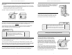
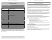
Pole Bracket
Saddle
U-Bolt
Figure A
Antenna Bracket Assembly
IMPORTANT: Incorrectly mounting the External Antenna to the mounting
bracket (see fi gure A) will impede performance. Ensure that the External
Antenna is properly positioned in the mounting bracket as pictured.
To mount External Antenna to a pole: Attach antenna to pole bracket
as pictured. Use U-Bolt to secure bracket to pole and fasten. DO NOT
mount to a metal pole.
To mount External Antenna to a fl at surface: Attach antenna to pole
bracket as pictured. Secure bracket to desired surface using provided
screws. Use of the Saddle and U-Bolt are not necessary for this option.
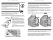
SECOND: Position Base and Indoor Antenna
NOTE: The zBoost Xtreme requires at least 15 feet of vertical separation
between the External Antenna and the Indoor Antenna. Generally,
increasing this distance (up to 40 feet) will increase the performance and
decreasing the distance will limit zBoost performance.
The Base Unit can be easily mounted on a wall by fi rst removing the bracket from the Base Unit
and using the provided mounting hardware to affi x to wall. Connect the Indoor Antenna to the 15
feet of RG-6. Then, using the TNC-F Adaptor, connect
the RG-6 to the Base Unit.
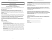
The Indoor Antenna should be mounted on a wall
facing the direction where increased coverage is
desired (See illustration below). Note that signal is
broadcast in a beamwidth of 70° horizontally and 60°
vertically from the front of the Indoor Antenna. Keep
the Indoor Antenna off fl oor and at least 3 feet away
from other cords, metal objects or other wireless
devices such as wireless routers or wireless access
points. The zBoost Xtreme performs best when there
are no obstructions between the Indoor Antenna and
your mobile device.
Note: The FCC requires that the panel antenna has
a minimum horizontal separation of 6 feet (2 meters)
from other CMRS (commercial mobile radio service)
devices.
Signal is emitted in a beam width of 70° horizontal and 60° vertical
zBoost Base Unit
Power Supply
s
t Ba
s
e
U
nit
TNC-F Adaptor
RG-6 (15ft)
Panel Antenna
Coaxial Cable