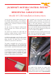
JACKSHAFT MOTOR-CONTROL SYSTEM FOR RESIDENTIAL GARAGE DOORS Model 815-RL Installation Instructions WARNING: To reduce the risk of injury to persons, use this operator only with a residential sectional door.
IMPORTANT INSTALLATION INSTRUCTIONS WARNING: To reduce the risk of Injury or death READ AND FOLLOW ALL INSTALLATION INSTRUCTIONS Install only on a properly balanced door. An improperly balanced door has the potential to inflict severe injury. Have a qualified service person make repairs to cables, spring assemblies, and other hardware before installing the opener. Remove all ropes and remove, or make inoperative, all locks connected to the garage door before installing opener.
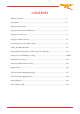
CONTENTS Product Overview .............................................................................................. 1 Description ........................................................................................................ 2 Fitting the Super-Drive ....................................................................................... 3 Fitting the Manual Over-Ride lever .................................................................... 5 Fitting the Control unit .........................
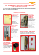
ZAP SUPER-DRIVE MOTOR-CONTROL SYSTEM FOR SECTIONAL DOORS The system includes model 800-R wall-mounting Control unit, Super-Drive jackshaft Operator, Motor Cover kit and Manual Over-Ride kit. PRODUCT OVERVIEW CONTROL UNIT model 800-R JACKSHAFT SUPER-DRIVE OPERATOR model 8472 Integrated Control unit with case mounted control button. This Control unit will power doors up to 15 square metres (160 square feet) in conjunction with model 8472 Operator.
JACKSHAFT MOTOR-CONTROL SYSTEM FOR RESIDENTIAL GARAGE DOORS Model 815-RL Installation Instructions The Zap 815-RL low voltage DC Motor-Control operates without limit switches and without a safety edge. It is preferable to set the overhead track angle at a gradient above horizontal to increase the influence of gravity on the initial movement of the door in the close direction.
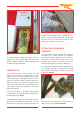
Pic 4 changes in door balance over a period of time. However springs should be checked and adjusted on each service visit at least once per year or 1500 door cycles, whichever is the sooner. FITTING THE SUPER-DRIVE OPERATOR The Super-Drive Jackshaft Operator kit includes an anti-torque arm, which prevents the operator rotating and which is bolted to the Super-Drive back plate using the motor cover back spacer provided and secured to a spare hole on the jackshaft bearing plate or onto the doorframe.
Align the Super-Drive keyway with the door shaft keyway and fit the key supplied with the package. Ensure that the two Allen screws are firmly tight and then tighten the lock nuts. (Pic 8) Pic 6 Next slide the Super-Drive assembly onto the door shaft and select a suitable hole in the torque arm to bolt it to the Super-Drive back plate using the spacer bush, which should pass through the lower slot in the Cover back. (Pic 7) The Cover back will be secured later.
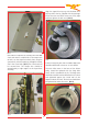
When fitting the Manual Over-Ride lever it is preferable to position the lever relative to the position of the end of the inner cable of the Bowden cable with the lever in the horizontal position. The second Allen screw, set at 90 degrees, should then be tightened and secured with the locknut. Now tighten the torque arm screws (Pic 10) When fitting the Over-Ride Lever ensure that the lever is horizontal when the cable tension is taken up.
Mark the hole positions for the Manual Over-Ride lever on the door track or frame in a convenient position with the lever held in the horizontal position. Drill two M5 or 7/32nd of an inch size holes. (Pic 13). Pic 13 Fit the M5 screws provided with the screw head on the inside of the track or doorframe. Fit the M5 nuts. Pic 15 When the lever tension is correct push the lever completely down to tension the V-Belt drive. (Pic 16) Secure the hook in the D-shackle of the over-ride cable.
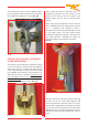
FITTING THE CONTROL UNIT The control unit lid can be temporarily secured to the case side screw positions to prevent it hanging by the cables during the setting up process. (Pic 18) Check that the control unit voltage, which is shown on the label on the side of the control unit case, is correct for the available single-phase supply voltage. The control unit model number has a suffix, which relates to the supply voltage.
be strapped to the Super-Drive Bowden cable with cable ties to allow both cables to seat neatly in the slot in the bottom of the Motor Cover. (Pic 20) Pic 21 The upper two pegs in the top edge of the cover back are next located in the two holes in the top edge of the cover front. (Pic 22). Pic 20 Do not cut or shorten the Motor Cable. Ensure that any unused cable is coiled and secured away from any moving parts, using the cable ties provided.
Pic 24 DO NOT PLUG THE POWER PLUG INTO THE SOCKET YET. Please ensure that any unused cable is coiled and secured using cable clips or cable ties provided. Pic 23 If the Control unit is to be wired permanently into the house wiring circuit, then the main 120 volt (Europe: 220 volt, UK 240 volt) supply lead, with plug attached, should be removed from the Control unit case as follows: CONNECTING THE MAIN A/C SUPPLY The Operator should be installed in accordance with local codes and national electric code.
7. The new supply wiring should be terminated to the GREEN connector block. The correct locations for the Live, Neutral and Ground wires are marked on the panel next to the GREEN socket. The new Black (live) wire should be terminated in the left hand terminal. The White (neutral) wire should be terminated in the center terminal and the Green (ground) wire should be terminated in the right hand terminal. (See Pic 24, previous page). Note that alternative wire colors apply to UK and Europe.
TESTING THE DOOR OPERATION When the basic wiring is complete the door operation may be tested. It may be helpful to fit an optional Plug-in Beeper module (part No. 850) (Pic 28), which sounds in conjunction with flashes Pic 30 SW1 SW2 SW3 SW4 SW5 SW6 SW7 Pic 28 of the Acknowledge LED. The beeper will sound at the start of each door movement and provides audible feedback during programming and door position calibration.
DOOR DIRECTION ASSESMENT The motor direction will depend on which side of the shaft the Operator is mounted. In order to assess the correct direction of movement of the door first release the Manual Over-Ride Lever and move the door manually to a half open position. Then re-engage the Manual Over-Ride Lever. Momentarily press the Control unit case lid button.
a build up of snow and ice or other surface material or subsidence of the ground surface. If the fully closed position varies significantly over a period of time it may be preferable to complete a new CALIBRATION RESET. If the door is subsequently moved by hand during a power supply failure the speed change points will be automatically re-established following confirmation of the ground position after a complete door cycle in both the open and close directions.
direction may be adjusted with the CLOSE SENSITIVITY preset. (Pic 37) Pic 39 If either of the preset controls is adjusted, the compression of the door edge seal will be affected and thus the position of the fully closed door may be different to the calibrated reference. In which case it may be necessary to complete a new Calibration Reset procedure.
12 VOLT TWO WIRE PHOTO-EYE WIRING See the wiring diagrams on pages 19 and 20. If two or more Photo-Eyes, or any other safety devices are fitted then each switching circuit should be wired in series. A 12 volt two wire Photo-Eye may be wired to the terminals marked at the top of the panel. (Pic 43). DIP switch No. 3 should be set to the ON position. Wiring diagrams for various types of photo-eye units are shown on pages 19 and 20.
If the safety circuit is interrupted whist the door is closing then the door will stop and reopen. If the safety circuit is interrupted whist the door is operating with the Auto-Close timer DIP switch No. 4 set to ON then the timer will reset during each interruption of the safety circuit, whilst the door is open. The Auto-Close function is not operational for the North American market. Pic 46 The Radio transmitter button will operate as: Press to open – Press to stop – Press to close – Press to stop.
An optional alternative programming sequence, using the case lid button, is provided for programming additional transmitters as follows: When the program button is pressed and held, a sequence of flashes of the Acknowledge LED follows at 4-second intervals. If a Bleeper is fitted then the Bleeper will sound with the flashes of the LED. 1. Close the door. 2. Press and hold the new transmitter button. 3. Press and hold the case lid button for at least 2.5 seconds.
AUTO-CLOSE TIMER PROGRAMMING Auto-Close regardless of the door re-opening after striking an obstruction. This function is not available for the North American market. It is preferable that the door should re-open and stay open following an obstruction strike. However it may be required for security reasons that the door should Auto-Close after re-opening, after hitting a large build-up of snow and ice in winter, in which case it will make two attempts to close onto the ice.
ZAP 800-R CONTROLLER WIRING – PULSE OPERATION WITH LIFT MASTER 412 HM RADIO " ; ! 2 75( 6+( $6( (&(,8(4 9,6+ 6+( " 21642//(4 :27 0756 &+$1*( 6+( (&(,8(4 )420 20(16$4: 23(4$6,21 62 2156$16 23(4$6,21 +( -703(4 /,1.,1* 2) 6+( 76376 '74$6,21 6(40,1$/5 5+27/' %( 64$15)(44(' 62 6+( 6(40,1$/5 1($4(56 6+( 276(4 ('*( 2) 6+( 3$1(/ 9+,&+ $4( 0$4.
ZAP 800-R – SAFETY WIRING CONNECTIONS – ZAP PHOTO-EYES ! ! ! ! 20
ZAP 800-R – SAFETY WIRING CONNECTIONS – NON-ZAP PHOTO EYES ! ! ! """"""""""""""""""""""""""""" """"""""""""""""""""""""""""""""" 21
FAULT FINDING GUIDE FAULT REASON & REMEDY 1. The door stops just after it has started in the open direction. A. The door movement is stiff due to the door running tight against the door frame in the fully closed position. In which case adjust the position of the roller wheel supports to ease the pressure of the door against the frame. B. The door is badly out of balance. In which case re-tension the counterbalance springs. C.
ZAP CONTROLS UK 100 Waterloo Boulevard Anglesey Business Park Cannock Staffordshire WS12 1NR United Kingdom