
User manual

APPLICATION
CONNECTIONSASSEMBLY
OPERATION
The timer is ready to work just right
after its appropriate connecting. The
light will be ON for the preset ON-time
duration after the timer is triggered by
means of a single pole push button.
When the preset time is over, the light
will be OFF automatically until the timer
is triggered once again. The light is softly
ON and OFF (soft start, 0.8 s). The sta-
ircase timer may be connected either to
three-conductor or four-conductor wiring.
Check carefully if the trigger and load
circuits have been connected correctly.
The timer may be damaged if connected
inappropriately. In case of the counter-in-
terlock lack the light is continuously ON
when the trigger push button is blocked.
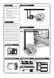
1. Disconnect the electric network by
means of an appropriate cut-off, cur-
rent-limiting circuit-breaker or sepa-
rator.
2. Check if there is no any voltage be-
tween power leads by means of an
appropriate gauge.
3. Place the ASP-01 device in a box
and connect wires accordingly to
electrical diagram.
4. Connect power supply circuit.
5. Adjust the light ON-time required by
means of the potentiometer.
CASING DIMENSIONS
UNIT DIAGRAM
TIME DIAGRAMS PRODUCT FAMILY
LOAD
The ASP-01 is a member of the ASx
staircase timer family.
μC
t
t t
b
r
o
w
n
r
e
d
b
l
a
c
k
b
r
ą
z
o
w
y
c
z
e
r
w
o
n
y
c
z
a
r
n
y
Device version:
01 – three - or four-conduc-
tor wiring
02 – built-in counter-intelock-
ing circuit
10 – dimmer function
Casing type:
M – single-module
N – surface-mounted
H – hermetic
P – for junction box mounting
Device symbol
24 V AC/DC version
for ASM-02 availalbe
ASx - xx (/24V)