
User manual

11
Leica MacroFluo – Assembly
2.2 Assembly sequence
Assemble the components in the following order:
– Stand: Base, column with focusing drive, focus-
ing stop, glass stage plate or optional spacial
stage (gliding stage, Leica MATS heating stage)
– carrier for the incident illuminator
– Incident light fluorescence illuminator
– Trinocular tube and two eyepieces
– Zoom system and objective, optional fine
focusing
– UV protection screen with arm and clamp
– Lamp housing with 100-W high-pressure mer-
cury burner, stray-light protection and supply
unit
– Instrumentation of nosepiece disc with filter
blocks
– For transmitted-light stand HL RC™: Fiber-optic
light guide with light source
– For motor focus: Handheld controller and/or
foot switch and poss. PC
– Optional digital camera with photo/video
adapters
– Electrical connections
Either the Allen keys included in delivery or the
integrated clamping screws are necessary for
assembly.
2.3 Stand assembly
The assembly of the transmitted-light stand
HL RC™ is described in the special M2-216-2
operating instructions. Additional stands and the
manual focusing drive can be found in the
M2-105-0 operating instructions on the supplied
CD-ROM and the motorized focusing drive in the
special M2-267-1 operating instructions.
Do not connect any devices to the supply
system at this time.
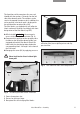
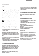
Focusing drive ➜ Base of stand
When using the motorized focus, it is
mandatory to read the separate M2-267-1 operat-
ing instructions, in particular the safety instruc-
tions.
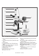
Fig. 2 see p. 12
왘 Attach the focusing drive (2.2) with column to the
base (2.1) according to the operating instruc-
tions. Tool: Allen key.
왘 Attach the focusing stop (2.3) on the stand col-
umn below the focusing drive using the clamp-
ing screw.
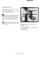
왘 Insert the glass stage plate or special stage
(2.5) in the stage opening.
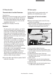
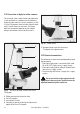
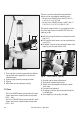
2.4 Incident light fluorescence illuminator
Carrier for the incident illuminator ➜
focusing drive
Fig. 3 see p. 13
Tool: Allen key.
왘 Fasten the carrier (3.1) with hexagon-head
screw (3.2) on the focusing drive (3.3).
왘 Fasten the incident illuminator (3.4) with
hexagon-head screw (3.5) to the carrier (3.1).