
Install Instructions
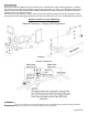
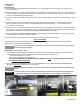
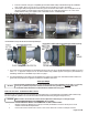

HORIZONTAL / SIDE WALL VENTING INSTALLATION - CATEGORY III & IV APPLIANCES
(See Illustrations 1 & 3 and Images 10 & 11 or 12 & 13 for Double Wall ZV-Clamp)
Prior to beginning the installation, loosely assemble all parts required to make sure all parts are present.
Review the venting requirements section in the appliance manufacturer's installation & operating manual to determine the
vent system configuration.
Select and apply the appliance adaptor to the flue outlet collar of the appliance.
Observing the sidewall vent termination rules on pages 3 & 4 and/or local building codes. Select the point of wall
penetration where the minimum 1/4 inch per foot of slope (6.4 mm per 305 mm) can be maintained.
1.
2.
3.
4.
i.
ii.
iii.
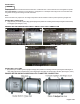
On a non-combustible wall, the pipe may be mortared in directly without using a wall thimble.
A wall thimble is required if terminating through a combustible wall.
A framed opening is required to insert the wall thimble halves and included adjustable pipe of Double Wall ZV-Clamp
Wall Thimble see Table 3 or 4 for part I.D. and associated opening. The thimble is adjustable for different wall
thicknesses consult Table 3 or 4 for appropriate part ID.
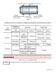
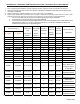
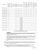
Table 3: Single Wall & Double Wall Snap Wall Thimbles
Page 8 of 28
4"-7" Wall 7"-13" Wall
2SVWT03 2SVWTM03
3" 1" 0” 5" x 5" 8" x 8" 480°F
2SVWT04 2SVWTM04
4" 1" 0” 6" x 6" 9” x 9” 480°F
2SVWT05 2SVWTM05
5" or 3”/5” 1" 0” 7" x 7" 10" x 10" 480°F
2SVWT064DW 2SVWTM064DW
4”/6” 1" 0” 8" x 8" 11" x 11" 480°F
2SVWT075DW 2SVWTM075DW
5”/7” 1" 0” 9" x 9" 12" x 12" 480°F
2SVWT06 2SVWTM06
6" 3” 0” 12” x 12” 15” x 15” 550°F
2SVWT07 2SVWTM07
7" 3” 0” 13” x 13” 16” x 16” 550°F
2SVWT08 2SVWTM08
8" or 6”/8” 3” 0” 14” x 14” 17” x 17” 550°F
2SVWT09 2SVWTM09
9" or 7”/9” 3” 0” 15” x 15” 18” x 18” 550°F
2SVWT10 2SVWTM10
10" or 8”/10” 3” 0” 16” x 16” 19” x 19” 550°F
2SVWT11 2SVWTM11
9”/11” 3” 0” 17" x 17" 20" x 20" 550°F
2SVWT12 2SVWTM12
12" or 10”/12” 3” 0” 18” x 18” 21” x 21” 550°F
2SVWT14 2SVWTM14
14" * or 12”/14” 3” 0” 20” x 20” * 23” x 23”
550°F 12"/14" Double
Wall, * 300°F or Non-
Combustible Material
14" Single Wall
2SVWT16 2SVWTM16
16" or 14”/16” 3” 0” 22” x 22” * 25” x 25”
* 300°F or Non-
Combustible Material
2SVWT18 2SVWTM18
18" or 16”/18” 3” 0” 24” x 24” * 27” x 27”
* 300°F or Non-
Combustible Material
2SVWT20 2SVWTM20
20" or 18”/20” 3” 0” 26” x 26” * 29” x 29”
* 300°F or Non-
Combustible Material
2SVWT22 2SVWTM22
22" or 20”/22” 3” 0” 28” x 28” * 31” x 31”
* 300°F or Non-
Combustible Material
2SVWT24 2SVWTM24
24" or 22”/24” 3” 0” 30” x 30” * 33” x 33”
* 300°F or Non-
Combustible Material
2SVWT26 2SVWTM26
24”/26” 3” 0” 32" x 32" * 35" x 35"
* 300°F or Non-
Combustible Material
Maximum Vent Gas
Temperature
Wall Thimble Part ID
Single Wall or
Double Wall-
Snap
(Inner/Outer)
Diameter
Outer Single
Wall or Double
Wall to
Thimble
Clearance
Thimble to
Combustible
Clearance
Combustible
Wall Inside
Opening
MINIMUM
Thimble
Outer Plate
Dimensions