
Install Instructions

AFFIXING THE FEMALE CONNECTOR ONTO THE SMOOTHCORE® FLEX
1.
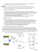
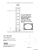
Measure 1 inch from the end of the usable length and mark around the flex every 90°
with a permanent marker joining the marks to make a continuous line. This is the
minimum insertion depth. (See Illustration 15)
2.
Perform a dry fit by inserting the flex into the female adaptor until it bottoms out.
Make note of where the marking lines up.
3.
Read the instructions on the supplied 10 oz. sealant tube (1 per Female Connector).
4.
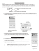
Trim the nozzle tip so that it is able to insert in-between the inner and outer wall of
the female connector and load tube in a caulking gun. (See Illustration16 & Image 27)
i.
It may be easier to remove the gear clamp from the brackets when
applying the sealant.
Illustration 16
5.
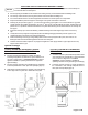
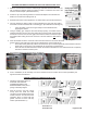
Using a caulking gun compress the tube liberally injecting a constant bead of
sealant in-between the inner and outer wall of the connector while circling entirely
around the connector. Do not leave gaps in the bead of sealant. Continue to inject
the sealant while circling around the connector until the channel is filled with the
sealant.
Image 27
6.
Place the female connector on the liner where the inner wall of the connector fits inside
the flex and the outer wall of the connector fits outside the flex. (See Images 28-31)
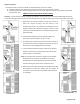
i.
Press down evenly and firmly until the connector lines up or is over the previously noted minimum insertion
depth mark on the flex liner. The sealant will rise as the liner is pressed down.
Once the liner has bottomed down smooth the sealant in-between the outer wall and the liner completely
around the minimum insertion point.
ii.
7.
Re-install gear clamp if removed in step 4.i. and tighten.
Image 28
Image 29
Image 30
Image 31
8.
Prior to installation, let the assembly cure for the minimum 24 hours or follow the cure time specified by the
approved sealant manufacturer.
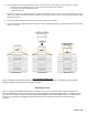
JOINING 2 LENGTHS OF SMOOTHCORE® FLEX
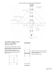
1.
Follow the Instructions above for
AFFIXING THE FEMALE
CONNECTOR ONTO THE
SMOOTHCORE® FLEX prior to
joining 2 assembly lengths.
2.
After the 24 hour cure time, simply
evenly insert the small end male
connector into the gasketed end of the
female connector. You will meet some
resistance when in contact with the
gasket. Continue to insert until fully
seated. (See Illustration 17)
Illustration 17
Illustration 28
20
Page 25 of 28