
Install Instructions
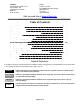

Page 5 of 18
A. The Z-FLEX SPECIAL STAINLESS VENT SYSTEM is for use only with appliances having a positive vent pressure of 8” of
water column or less.
B. Except for installation in one and two family dwellings, a venting system that extends through any zone above that on which the
connected appliance is located shall be provided with an enclosure having a fire resistance rating equal to or greater than that
of the floor or roof assemblies through which it passes
C. Do not wrap the pipe with insulation or cladding or place any type of insulation within the required air spaces surrounding the
venting system.
D. A termination must be used on all installations to assure proper operation and to prevent debris from entering the venting
system.
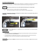
E. Vertical runs must use a fire-stop as a lateral support at each ceiling level and at least one support at the base of the vertical run
where required by the appliance manufacturer. For vertical runs exceeding 16 ft (4.88m), a support collar is required at 16 ft
(4.88m) intervals. Support horizontal runs using loose fitting metal straps as hangers and similar supports at each elbow.
F: It is recommended that vertical and horizontal drain tees with 3inch p-traps be installed on long vent systems in order to
eliminate the system of condensate as quickly as possible.
JOINT PROCEDURE
The female end of each Z-Vent Model SVE IV component incorporates a self sealing gasket. Examine all components for
damage to ensure that gasket integrity has remained intact during shipping.
Joint connections not meeting the full insertion can leak causing severe personal injury, death or
substantial property damage.
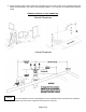
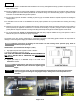
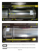
SINGLE WALL: (see illustration #1 & images 1, 2 & 3)
1. Align pipes and push them together to indent or at least…
1.75 inches for diameters 3 inch thru 12 inch.
PIPE JOINT NOT MEETING THE MINIMUM ABOVE PARAMETER IS
NOT
FULLY SEATED AND IS THEREFORE AN UNACCEPTABLE
CONNECTION.
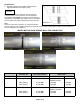
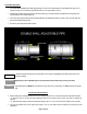
2. Tighten gear clamp to a minimum torque of 40 in/lbs. and a
maximum of 50 in/lbs.
Over tightening the gear clamp can cause the seal to
fail. DO NOT use power tools when tightening gear
clamps.
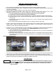
Fasteners (screws, rivets, etc.) must not penetrate the components of the single wall system either
when joining pipes and fittings or using support straps. Drilling holes in the components is not
permitted.
Image 1 Image 2 Image 3
NOTICE
WARNING!
WARNING!
DANGER!