
Install Instructions

Page 10 of 18
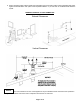
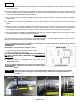
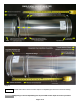
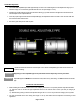
Double Wall Adjustable:
¾ The Double Wall Adjustable Pipe adds approximately 9 inches to the overall length PLUS the adjustment range up to a
maximum range of 6-1/2 inches for pipe diameters 3in thru 12in (see images 13 & 14).
¾ Following the double wall pipe connection instructions above (pg. 6) make certain that the pipes are inserted to the full
insertion depth for the required diameter.
¾ Once the proper length is achieved with the adjustable pipe, the adjustment sleeve can slide to close the outer wall until
the inner bead clicks with the locks.
¾ Secure the gear clamp to lock slider in place.
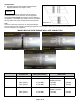
Image 13 Image 14
Installer shall mark the minimum insertion depth on the double wall adjustable pipe small end and insert to at
least this marking.
Neglecting to insert adjustable pipe to the prescribed insertion depth may result in joint failure.
Adjustable pipes are NEVER to be inserted into a tee, elbow or any other fitting. It is ONLY inserted into another
pipe.
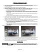
Condensate Tube Installation:
¾ When installing the condensate tube be sure to form a trap by means of a 3 inch (76 mm) diameter loop filled with water.
a) This tube must be 3/8 inch ID high temperature silicone for at least the first 6 inches (152 mm) for category III
systems.
b) Alternate tubing having a minimum temperature rating of 300˚F ≈ 150˚C may be used on category II & IV systems.
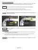
¾ The tube is attached with a hose clamp (see images 15 & 16). The effluent must be disposed of according to local
regulations.
NOTICE
WARNING!
WARNING!