R2 Extender Quick Installation Guide V 1.
Copyright Copyright © 2008 all rights reserved. No part of this publication may be reproduced, adapted, stored in a retrieval system, translated into any language, or transmitted in any form or by any means without the written permission of the supplier. About the Installation Guide This Installation Guide is intended to guide professional installer to install the R2 Extender. It includes procedures to assist you in avoiding unforeseen problems.
Chapter 1 Introduction Introduction The R2 Extender is a high-performance outdoor-deployable wireless bridge that provides wireless connectivity among multiple network locations. It supports Base Station, CPE, PTP and PTMP connectivity. Moreover, the R2 Extender has a built-in 23dBi planar antenna that can deliver up to a 40Km connection. An external antenna may also be used to improve signal quality, extend distance and flexible for local coverage applications.
Chapter 2 Preparation before Installation This chapter describes safety precautions and product information you have to know and check before installing R2 Extender. Professional Installation Required 1. Please seek assistance from a professional installer who is well trained in the RF installation and knowledgeable in the local regulations. 2. The R2 Extender is distributed through distributor and system installer with professional technicians and will not be sold directly through retail store.
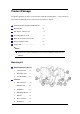
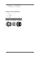
Product Package The product package you have received should contain the following items. If any of them are not included or damaged, please contact your local vendor for support. R2 Extender with integrated 23dBi antenna ×1 Mounting Kit ×1 PoE Injector & Power cord ×1 Grounding Wire w/ screw ×1 Water Proof RJ-45 Connector Kit ×1 Quick Installation Guide ×1 Product CD………………………..
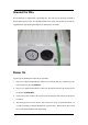
10. Wood Screw ×4 (for Wall Mount) 11. Wall/Gyprock Plug ×4 (for Wall Mount) Waterproof RJ-45 Connector Kit 1. Gland ×1 2. Sealing Nut ×1 3.
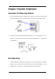
Chapter 3 System Installation Assemble the Mounting Bracket 1. Place the main bracket into the seating and use a spanner to fasten the bracket to the R2 8 and M5 washers ○ 9 provided in the hardware packets; Extender with M5×16 screws ○ 2. 2 to the T-form bracket ○ 1 via a Assemble the main bracket by placing articulation pole ○ 4 screw through the insertion axe and fix with the M8 washer ○ 5 , spring washer M8×90 ○ 6 and M8 nut○ 7 ; ○ Pole Mounting 1.
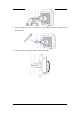
2. 4 and washers ○ 5 through the drill holes and main bracket Fasten two M8×80 screws ○ with a spanner; 3. Adjust the antenna for appropriate tilt / vertical orientation.
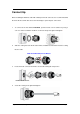
Connect Up Before installing the Ethernet cable with a waterproof RJ-45 connector, it is recommended that the Cat-5 RJ-45 coaxial cable be used for the bridge to power injector connections. 1. To connect to the hole labeled PoE+Data, open the black cover in advance by using a coin or a slotted screwdriver and then screw in the body of the gland and tighten. 2. Slide the sealing nut to the RJ-45 cable from its middle breach and then insert the sealing into the cable.
Ground the Wire The R2 Extender is shipped with a grounding wire. The unit must be properly grounded to protect against power surges. The grounding point can be found on the bottom of the unit. It is supplied with an appropriate grounding lug for attachment to the ODU. Power On To power up the R2 Extender, follow the steps bellow: 1. Plug a user-supplied Cat-5 Ethernet cable from your wired LAN (or a computer) into the power injector RJ-45 jack (DATA IN); 2.
Warning: Make sure PoE is correctly connected to the RJ-45 port on the R2 Extender labeled PoE+Data.
Chapter 4 Configuration Connect the R2 Extender to a Local Computer If you are configuring the R2 Extender locally (without connecting its power injector to a wired LAN), connect a PC to the power injector’s Ethernet port using a Category 5 Ethernet cable. 1. Assign a static IP address to your PC which is in the same network segment with the R2 Extender. As the default IP address of this unit is 192.168.1.1, you may choose from 192.168.1.2 to 192.168.1.254. 2.
R2 Extender’s still initializing System ready Note: Considering convenient configuration, it is recommended to configure local and remote R2 Extender respectively on two computers. z TTL time may vary depending on the operating system..
How to Establish Wireless Bridge Mode The R2 Extender supports four operating modes, which are Base Station, CPE, Peer-to-Peer (CSMA) and Peer-to-Peer (TDMA). Normally, Wireless Bridge is the typical mode on this unit. Here we will illustrate how to establish wireless bridge connectivity with R2 Extender. Enter the user name (admin) and password (password) to login and make configurations. Note: Due to browser’s security trusted sites, 192.168.1.1 might not able to be opened.
192.168.1.2 and set the IP Subnet Mask on both as 255.255.255.0 Warning: Each IP address is unique within a LAN, otherwise IP collision may occur! Open “Radio” in “Wireless” and you will find the default operating mode is Peer-to-Peer (CSMA). Select RF1(WLAN1) or RF2 (WLAN2) as Bridge to make the following configuration. Here we take RF1 as an example. Se select Peer-to-Peer (CSMA) operating mode and keep the Channel/Frequency and Bandwidth on both R2 Extenders identical. Click “Apply” to save settings.
Login the Web-based interface of remote R2 Extender, open “About” in “System” and record the wireless MAC address of it, either WLAN 1 or WLAN 2 MAC Address. Login the Web-based interface of local R2 Extender and open “Peer-to-Peer Setup” in “Wireless”.
Warning: The MAC address on the housing of R2 Extender is the ETH MAC address; therefore it can not be used in Peer-to-Peer links. The IP address of your PC should be in the same network segment to the one of bridges. Use ping to check whether the link between the two R2 Extender is OK. R2 Extender A R2 Extender B To get a better wireless connectivity, antenna alignment is strongly recommended after both R2 Extenders are installed long distance apart.
in “Wireless”. Select RF1 and hit “Align Antenna” button, an antenna alignment tool will popup. Specify the Target RSSI and click “Start” to begin the antenna alignment. Fix the local antenna and adjust the remote antenna elevation and horizontal direction. During the adjustment, observe “Current RSSI” in local R2 Extender. Fix the remote antenna when it reaches your expectation. Usually, RSSI between -60 and -70dBm indicates rather good signal strength.
Chapter 5 Troubleshooting This chapter provides troubleshooting procedures for basic problems with the R2 Extender. Q 1. What if my R2 Extender fails to connect to the remote one? • Ethernet Link: Check the availability of power to the bridge by observing the LED status on the power injector. - Green: The R2 Extender is connecting to the backhaul network.
Chapter 6 Service Information If you have any further trouble using the R2 Extender or you would like to require additional support, you may visit our website at www.zcom.com.tw/rpc or you may contact us as below for support: Z-Com, Inc. Taiwan 7F-2, No.9. Business RD. Center Industrial Park FAE Support Hsinchu ,300 Taiwan support@zcom.com.tw I Prosperity Tel: +886-3-5777364 Sales Contact Science-Based Fax:+886-3-5773359 info@zcom.com.tw Zcomax Technologies, Inc.