Document No : YRL_UM_EN_2101_V1.2 User Manual YRL Series YRL2-05 l YRL2-10 l YRL2-20 l YRL3-05 l YRL3-10 l YRL3-20 No part of this manual may be reproduced in any form without the written permission of Yujin Robot Co., Ltd. Yujin Robot Co., Ltd. assumes no responsibility for errors or omissions or any damages resulting from the use of the information contained in it. Copyrightⓒ2020. YUJIN ROBOT Co., Ltd. All Right Reserved.
How to Use This manual provides important information for using the YUJIN LiDAR. Please read it before using this product to operate it correctly. The operating instructions are intended to be used by qualified specialists. Manual Symbols In this manual, symbols are used to mark safety information. Please refer to the following for safe use. Warning Indicates handling requirements that if not maintained might lead to fatality or serious injuries.
Contents 1. About the Product 1.1. Product Description 1.2. Product Components 1.3. Product Diagram 1.4. Features 4 4 4 5 5 2. Key Functions 6 2.2. Performance 8 2.1. Specifications 2.3. Dimensions 2.4. Pin Assignment 3. Operation and Programming 3.1. Installing the YUJIN LiDAR Viewer 3.2. Connecting and Starting 3.3. YUJIN LiDAR Viewer Function 4. Driver Interface (API) 4.1. Parameter 4.2. Parameter Input and Output Function 4.3. Data Output Function 4.4. LiDAR Input and Output Function 4.5.
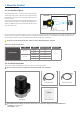
1. About the Product 1.1. Product Description The YUJIN LiDAR YRL Series is a laser sensor that scans horizontally and vertically to detect objects. The sensor uses a single laser (wavelength: 905 nm), and a mirror moves through the motor and detects the entire scan area. Distance measurement uses the time of flight (ToF) method. The ToF method calculates the distance to an object by measuring the time it takes for a LiDAR laser pulse to be reflected from the surface of the object back to the source.
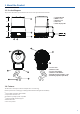
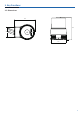
1. About the Product 1.3. Product Diagram The product is divided into optical and bottom. Please refer to the part names below for details. ① Optical Window ② Middle Cover ③ Bottom Cover ④ LED Label ⑤ Status Display LED Optical Bottom ⑥ Power Cable ⑦ Ethernet Cable ⑧ Power Cable Rubber ⑨ Ethernet Cable Rubber ⑩ Alignment Support Mark(0˚ axis) ⑪ Mounting Tap M3 (Depth:4mm) 1.4. Features The YRL Series is developed on the basis of Yujin Robot’s core technology.
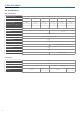
2. Key Functions 2.1. Specifications Basic Specification Environment Condition Model Name Measurement Range (Kodak R-27 Gray Cards White 90%) YRL2-05 YRL2-10 0.1~5m 0.1~10m - Vertical Angle Light Source YRL3-10 0.1~5m 0.1~10m YRL3-20 0.1~20m 270 ° 90° (+/- 45°) Laser Diode Class 1, eye safety (IEC 60825-1:2014) Laser Class 905 nm Laser Wavelength Horizontal Scan Frequency - Vertical Scan Frequency Range Resolution Horizontal Angular Resolution 20 Hz <10mm 0.
2.
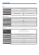
2. Key Functions 2.2. Performance 1) Output Data The YRL Series can collect 13,000 point cloud per second, and each point cloud contains the following information.
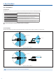
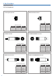
2. Key Functions 2.3. Dimensions 85.0 91.4 44.0 65.0 85.0 70.0 44.0 65.
2. Key Functions 2.4.
3. Use of the Product 3.1. Installing the YUJIN LiDAR Viewer Install the YUJIN LiDAR referring to the recommended specifications below: 3.1.1. Recommended Specifications Recommended Specifications System more than 1GHz, 64bit processor Memory 1 GB OS Storage Resolution Windows 10 64 bit, Ubuntu 18.04 64 bit 450 MB 1024 x 768 The LiDAR may not be installed properly if it fails to meet the recommended specification. 3.1.2.
3. Use of the Product 3.2.2. Using the program YUJIN LiDAR data appear on the viewer automatically when the connection is made successfully. You can also get a visualized data you want by changing configuration values of the viewer. 3.3. Name and Functions of the YUJIN LiDAR Viewer Once the YUJIN LiDAR is connected to the viewer, you can see the point cloud data on the screen in real time. Various settings are availvable for users to see the visualized data you want. 3.3.1.
3. Use of the Product 2) Setting Tab 2-1) YUJIN LiDAR Setting ● ● ● ● YUJIN LiDAR IP : You can change the IP value. You can either connect or disconnect the program and product with the connection and disconnect button. You can verify status information about the product connected (status, serial number and hardware version). You can change the IP address of your LiDAR by clicking the setting icon. 2-2) Setting Viewer 2-2-1) Visualization : Data processed are visualized in the screen.
3. Use of the Product 2-2-4) Position and direction of LiDAR : The position and direction of LiDAR can be set on a screen. Input the actual sensor height in the Z value of the LiDAR Position to see the actual view. If the LiDAR is on the bottom, the sensor height is 0.06 m. Default value Minimum value Maximum value 99.00 Coordinate X of the LiDAR position Y 0.00 -99.00 99.00 Coordinate Y of the LiDAR position Z 0.06 -99.00 99.00 Coordinate Z of the LiDAR position Roll (Degree) 0.00 -360.
3. Use of the Product 2-3) Setting the Point Cloud 2-3-1) Data setting Function Vertical data range Cloud size Noise filter Stack Default value Min. value Max. value Description 3.00 -99.00 99.00 Vertical data range to be visualized. 0.01 0.00 10.00 Scattered noise is filtered. 1.40 50 0.00 0 10.00 1500 Size of the point cloud. The data scanned are tied, while the LiDAR turns around.
4. Driver Interface (API) Scan data can be fabricated and collected by the API provided after the YUJIN LiDAR driver is installed. The driver and sample can be downloaded from the website of YUJIN or GitHub (github.com/yujinrobot/yujin_lidar). 4.1. Parameter It describes the variable values used by the API. The mark before each number is the function given only to the 3D LiDAR No. 16 Parameter Name Default Explanation 1 ip_address 192.168.1.250 Input IP address to the driver.
4. Driver Interface (API) 4.2. Parameter Input/Output Functions It can bring forth the variable value of a driver through the API or change the value. The mark before each number is the function given only to the 3D LiDAR No.
4. Driver Interface (API) 4.3. Data Output Functions It can verify the status and data of YUJIN LiDAR through the API. The mark before each number is the function given only to the 2D LiDAR No. Parameter Name Unit Explanation 1 void getConnectionState(bool &connection_state) N/A Check connection status. (False, True) 2 void getRPS(double &rotation_per_sec) N/A Returns rotational speed of LiDAR.
4. Driver Interface (API) 4.5. Error Code Table The mark before each number is the function given only to the 3D LiDAR No. Error Code 1 A 2 Error Name LED Solution Description Power Error Red Customer service inquiry. Power Error B Horizontal rotation error Red Customer service inquiry. Mirror horizontal rotation error *3 C Vertical movement error Red Customer service inquiry. Mirror vertical movement error 4 D Temperature measurement error Red Customer service inquiry.
To improve quality, the product’s design and specifications may change without prior notice. YUJIN ROBOT Co., Ltd. | INNOVATION FOR A BETTER WORLD Address : 33, Harmony-ro 187 beon-gil, Yeonsu-gu, Incheon, Republic of Korea TEL : +82-32-550-2322 FAX : +82-32-550-2301 E-mail : lidar@yujinrobot.com www.yujinrobot.