SIC-A series Air-cooled Water Chillers Date: Feb, 2006 Version: V1.
Contents 1. General Description 1-1 2. Technical Specifications 2-1 2.1 SIC-A Series Outer Dimensions 2-1 2.2 SIC-A Series Specification List 2-7 3. Main Functions 3-1 3.1 Working Principle 3-1 4. Safety Regulations 4-1 5. Installation 5-1 5.1 Installation Instructions 5-1 5.2 Installation Space 5-2 5.3 Schematic Drawing of Installation 5-3 6. Operation Guide 6-1 6.1 Control Panel 6-1 6.2 System Startup 6-3 6.3 System Shut Off 6-4 6.4 Temperature Controller 6-4 7.
Contents 9.2 SIC-A Series Parts List 9-3 9.3 Main Components Functions 9-11 10. Electrical Circuit Diagram 10-1 10.1 SIC-3A/4A/5A-P Electrical Circuit Diagram 10-1 10.2 SIC-3A/4A/5A-P Electrical Components List 10-4 10.3 SIC-8A/10A/12.5A/15A-P Electrical Circuit Diagram 10-7 10.4 SIC-8A/10A/12.5A/15A-P Electrical Components List 10-10 10.5 SIC-20A/25A-P Electrical Circuit Diagram 10-14 10.6 SIC-20A/25A-P Electrical Components List 10-16 10.
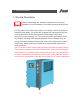
1. General Descriptoin 1. General Description Please read through this operation manual before using and installation to avoid damage of the machine and personal injuries. The SIC series of air-cooled water chillers use a single closed-loop design for pressurised refrigerant. All models are equipped with compressor and motor overload protection, phase shortage and reversal alarms, anti-freeze thermostat, pressure gauges, etc. They feature excellent performance and a long lifespan.
1. General Descriptoin Main Features: 1. Cooling capacity from 7 o to 35 C. 2. Stainless insulated water tank. 3. Equipped with anti-freeze thermostat. 4. Environment-friendly R407C refrigerant used as standard for efficient cooling. 5. Refrigeration loop controlled by high and low pressure switches. 6. Compressor and pump overload relays. 7. Tube-fin condenser design for excellent heat transfer and rapid cooling. 8. Tube-in-shell evaporator for excellent cooling.
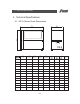
2. Technical Specifications 2. Technical Specifications 2.
2. Technical Specifications 2.2 SIC-A Series Specification List Model SIC-3A-P Item SIC-4A-P SIC-5A-P SIC-8A-P SIC-10A-P SIC-12.5A-P SIC-15A-P SIC-20A-P SIC-25A-P SIC-30A-P SIC-40A-P SIC-45A-P SIC-50A-P Parameter 50Hz 7.69 10.71 13.5 19.08 25.56 31.41 38.79 51.12 62.82 77.58 102.24 113.94 60Hz 9.12 12.8 16.2 22.8 30.6 37.6 46.5 61.2 75.3 93.1 122.4 136.6 150.
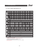
3. Main Functions 3. Main Functions 3.1 Working Principle SIC-A air-cooled water chillers include compressor, condenser, thermostatic expansion valve, and evaporator four main components. The system adopts a single closed-loop design for refrigeration system. Refrigerant is alternatively changed from gaseous to liquid state to absorb or release heat thus a cooling effect is achieved. 4 3 C D 6 Process water E 13 11 2 5 8 16 9 B A 7 10 12 14 1 15 Direction of refrigerant No. Name No.
3. Main Functions When the machine is started, compressor (1) starts working. Refrigerant is compressed into high pressure and high temperature gas in the process from A to B. In the process from B to C and D, this high pressure and high temp. gas is cooled when it is passing through the condenser (2) and changed into liquid. Heat is taken away by the cooling water.
4. Safety Regulations 4. Safety Regulations Operation should be carried out according to the safety regulations this manual to avoid damage of the machine and personal injuries. Abide by the following regulations during operation. Electrical installation should done by qualified electricians. Main switch and control should be turned before service and maintenance.
4. Safety Regulations Transportation and storage of the machine Transportation 1) SIC-A series are packed in crates or plywood cases with wooden pallet at the bottom, suitable for quick positioning by fork lift. 2) After unpacked, castors equipped on the machine can be used for ease of movement. 3) Do not rotate the machine and avoid collision with other objects during transportation to prevent improper functioning.
4. Safety Regulations 4) This equipment works normally in the environment with altitude within 3000m. 5) At least a clearance of 1m surrounding the equipment is required during operation. Keep this equipment away from flammable sources at least two meters. 6) Avoid vibration, magnetic disturbance at the operation area. Rejected parts disposal When the equipment has run out its life time and can not be used any more, unplug the power supply and dispose of it properly according to local code.
5. Installation 5. Installation Read this chapter before installation. Install the machine according to following steps Air-cooled water chillers should be installed in an environment that has good ventilation, such as draughty area against the window. Ambient temperature should not be more than 35 if it is installed indoors. Use exhaust pipe to conduct the hot air produced by the chiller to the outside. If the chiller is installed outdoors, protective cover should be used. 5.
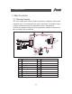
5. Installation 5.2 Installation Space During installation of the machine, keep at least 500mm installation space around the machine as shown by the picture. Do not install the machine in a position crowded with other objects. This would cause inconvenience to operation, maintenance and repair. Do not sit on the machine. Make sure the machine is in an environment with good air convection.
5. Installation 5.3 Schematic Drawing of Installation Water chiller 7 Cooling water circulation Process water outlet Process water inlet Cooling water pump 9 Cold water circulation Water discharge port 10 Mould cooling Water refill port 11 Cooling chamber Cooling tower 12 Hydraulic oil cooling 5.4 Power Supply Make sure that power supply is the same as required before installation. SIC-A series should be connected with 3 400V power supply and earth wire.
6. Operation Guide 6. Operation Guide 6.1 Control Panel 1 2 11 3 4 5 6 7 No. Name 1 Power indicator 2 Anti-phase indicator 8 9 Functions 10 Remarks Connect through power supply and Note! Do not disassemble any electrical components or terminals turn on the main switch, the in case of electrical shock. indicator will becomes bright. It is used to indicate phase reversal or phase shortage. The buzzer sounds and system stops working.
6. Operation Guide No. Name Functions Remarks 3 Pump overload indicator When pump current exceeds the limits, this indicator becomes bright. The buzzer sounds and system stops working. Check if the motor is blocked or the bearing is broken. If motor works normally, please check if the setting current of the overload relay in the control box is set too low. After the above measures are taken, wait for about 1 minute, then press the blue "reset" button to reset the alarm.
6. Operation Guide 6.2 System Startup 1) Turn on the main switch. ON OFF 2) Turn on the pump. 3) Turn on the compressor. 4) Set process water temperature (Neglect this step if temperature is already set). Press to increase or decrease water temperature. For this series of water chillers, process water temperature should be set as 7 (never set below 5 ). 5) Anti-freezing setting: anti-freezing switch equipped (setting value 5 ).
6. Operation Guide 6.3 Machine Shut Off 1) Turn off the compressor. 2) Turn off the pump. 3) Turn off the main switch. Note! Avoid electrical shock when main switch is turned on. Note! In order to reduce the possibilities of machine damage and prolong the life, shut off the machine with correct methods. 6.4 Temperature Controller Increase value Temperature setting Decrease value Temperature hysteresis value Temperature display 6.4.
6. Operation Guide key Press or to increase or decrease the values of parameters. Press and hold up to change the parameter values at a quick. The biggest and smallest values have been set in the "SETUP". Change it according to the first part of 6.4.2 and the following instruction. 2) key When the MTR works normally, press key, the screen display"L1", display the setting value two seconds later. If "L1" achieve the settingvalue, the control output RL1 changes from On to Off.
6. Operation Guide 2). Parameter instruction v SP The lowest setting value(-50 OC~+50 OC) ;(0~100%) O SP The highest setting value( vSP~+150 C) ;( vSP ~100%) rt1 The lowest turn off time of Rl1. The lowest time interval of setting turn on and turn offRL1can be adjusted between zero and ten minutes. Pf1 The time of probe head malfunction, the working stage of RL1 On/Off ADj The compensate value of the input value.
7. Service & Maintenance 7. Service & Maintenance All repair work should be done by qualified personnel only to avoid damage to the machine or personnel injury. In order to operate the machine rightly and safely, please caution the matter as follows: 1) Do not turn off the main power switch to stop the machine,except emergency situation.
7. Service & Maintenance After the vacuum pumping, connect the air pipe of the refrigerant tank to the liquid filling thimble valve, and fill the refrigerant into the air return pipe. Watch the change of the weight displayed by the electronic scale, and stop filling the refrigerant immediately when receiving the schedule weight.
7. Service & Maintenance 7.2 Maintenance of the subassemblies 7.2.1 Condenser SIC-A series water chillers use the air cooled condenser with ferrule installed openly, in the using time, it hard to avoid any dust and sundries ,which will influence the heat emission effect, so it is necessary to clean the condenser at fixed periods in order to keep its working performance. Use brush, dust catcher or compressed air to clean the wings and copper pipe. Then use the low pressure water to cascade the tray pipe.
7. Service & Maintenance 7.
8. Trouble Shooting Faults 1. No power supply display or phase reversal 2. The pump over loading 3. The compressor over loading 4.The high pressure is too high 5. The high pressure is too low 6. The low pressure is too low The action of the protection units The protection units have no action The loader trips The loader trips The high pressure switch trips The protection units have no action The low pressure switch trips The possible fault analysis Solution A.
8. Trouble Shooting Faults 7. The low pressure µ Í Ñis¹too¹high ýµ ¸Í 8. The compressor overheat 9. The chassis of the air return pipe and the compress or frost over. 10 The compressor can not start up or trips after starting up The action of the protection units The possible fault analysis The protection units have no action A. The cooling load is too big B. The power of the compressor decreases. C. The open scale of the expansion valve is too big D.
9. Assembly Drawing 9. Assembly Drawing 9.1 SIC-A Series Assembly Drawing ------------------------------------------------- 9-2 9.2 SIC-A Series Parts List ---------------------------------------------- 9-3 9.
9.
9. Assembly Drawing 9.2 SIC-A series parts list No. of the materiel N0.
9. Assembly Drawing No. of the materiel N0.
9. Assembly Drawing No. of the materiel N0.
9. Assembly Drawing No. of the materiel N0.
9. Assembly Drawing No. of the materiel N0.
9. Assembly Drawing No. of the materiel N0.
9. Assembly Drawing No. of the materiel N0.
9. Assembly Drawing No. of the materiel N0.
9. Assembly Drawing The major parts and their functions 9.3.1 compressor Compress and transport the refrigeration steam and produce the low pressure in the evaporator and the high pressure in the condenser, so the compressor is the heart of the whole system. The compressors of our company are the two types of scroll and piston. The power of the generic compressors is 25 to 30 percent of the ice water machine's refrigeration capacity. 9.3.2 condenser 1 ) .
9. Assembly Drawing 9.3.4 The heat expansion valve 1). The heat expansion valve is used to take the effect of throttle and pressure relief, and also adjust the flow quantity of the cooling agent going into the evaporator. 2). The heat expansion valve is usually installed in front of the evaporator. 9.3.5 evaporator 1). The evaporator is the equipment which output the refrigerating capacity, in which the cooling agent absorb the heated of the cooled objects and gain the aim of refrigeration. 2).
10.Electical Circuit 10. Electrical Circuit 10.1 SIC-3A/4A/5A-P Electrical Circuit 10.1.1 control circuit principle diagram Pump switch Pump motor contactor Compressor Compressor Crankcase heating zone Contactor Fan motor contactor Obligate to connect the optional constant close point of the protector. When not need to connect the protector, it can connect short. 10.1.2 components layout Stand for the power obligate for the optional.
10.Electical Circuit 10.1.3 SIC-3A-P Main circuit principle diagram Pump motor Compressor Fan motor 10.1.
10.Electical Circuit 10.1.
10.Electical Circuit 10.2 SIC-3A/4A/5A-P Electrical components list 10.2.1 SIC-3A-P Electrical components list No . Parts number Name Breaker Main power switch Contactor Contactor Contactor Temp. Controller Fitting of the Temp.
10. Electrical Circuit 10.2.2 SIC-4A-P Electrical components list No . Specificatons Name Parts number Breaker Main power switch Contactor Contactor Contactor Temp. Controller Fitting of the Temp.
10. Electrical Circuit 10.2.3 SIC-5A-P Electrical components list No . Parts number Name Breaker Main power switch Contactor Contactor Contactor Temp. Controller Fitting of the Temp.
10. Electrical Circuit 10.3 SIC-8A/10A/12.5A/15A-P Electrical Circuit 10.3.1 Control circuit principle diagram Pump switch Pump motor contactor Compressor Crankcase heating zone Compressor switch Compressor contactor Fan motor Contactor Fan motor Contactor Obligate to connect the optional constant close point of the protector. When not need to connect the protector, it can connect short. 10.3.2 Components layout diagram Stand for the power obligate for the optional.
10. Electrical Circuit 10.3.3 SIC-8A-P Main circuit principle diagram Compressor Pump motor Fan motor 10.3.
10. Electrical Circuit 10.3.3 SIC-12.5A-P Main circuit principle diagram Pump motor Compressor Fan motor Fan motor 10.3.
10. Electrical Circuit 10.4 SIC-8A/10A/12.5A/15A-P Electrical components list 10.4.1 SIC-8A-P Electrical components list No . Name Parts number Breaker Main power switch Contactor Contactor Contactor Temp. Controller Fitting of the Temp.
10. Electrical Circuit 10.4.2 SIC-10A-P Electrical components list No . Name Specificatons Parts number Breaker Main power switch Contactor Contactor Contactor Temp. Controller Fitting of the Temp.
10. Electrical Circuit 10.4.3 SIC-12.5A-P Electrical components list No . Name Specificatons Parts number Breaker Main power switch Contactor Contactor Contactor Temp. Controller Fitting of the Temp.
10. Electrical Circuit 10.4.4 SIC-15A-P Electrical components list Name No . Specificatons Parts number Breaker Main power switch Contactor Contactor Contactor Temp. Controller Fitting of the Temp.
10. Electrical Circuit 10.5 SIC-20A/25A-P Electrical Circuit 10.5.1 Control circuit principle diagram Pump switch Pump motor contactor Compressor Crankcase heating zone Compressor Crankcase heating zone Compressor switch Compressor contactor Compressor Contactor Fan motor contactor Fan motor contactor Obligate to connect the optional constant close point of the protector. When not need to connect the protector, it can connect short. 10.5.
10. Electrical Circuit 10.5.3 SIC-20A-P Main circuit principle diagram Pump motor Compressor Compressor Fan motor Fan motor 10.5.
10. Electrical Circuit 10.6 SIC-20A/25A-P Electrical components list 10.6.1 SIC-20A-P Electrical components list No . Name Parts number Door lock breaker Contactor Contactor Contactor Temp. Controller Transformer Fitting of the Temp.
10. Electrical Circuit 10.6.2 SIC-25A-P Electrical components list No . Specificatons Name Parts number Door lock breaker Contactor Contactor Contactor Temp. Controller Transformer Fitting of the Temp.
10. Electrical Circuit 10.7 SIC-30A-P Electrical circuit diagram 10.7.1 Control circuit principle diagram Pump switch Pump motor contactor Compressor Crankcase heating zone Compressor Crankcase heating zone Compressor switch Compressor contactor Compressor Contactor Fan motor contactor The thermal protector of compressor Fan motor contactor Obligate to connect the optional constant close point of the protector. When not need to connect the protector, it can connect short. 10.7.
10. Electrical Circuit 10.7.
10. Electrical Circuit 10.8 SIC-30A-P Electrical components list Name No . Specificatons Parts number Door lock breaker Contactor Contactor Contactor Fitting of the compressor Protector of the compressor Temp. Controller Transformer Fitting of the Temp.
10. Electrical Circuit 10.9 SIC-40A-P Electrical circuit diagram 10.9.1 Control circuit principle diagram Pump switch Compressor switch Pump motor Compressor Crankcase heating zone (obligate) Compressor Crankcase heating zone (obligate) Compressor Crankcase heating zone (obligate) Compressor Compressor Overheat protector relay Overheat protector relay The motor of the fan contactor The motor of the fan contactor Obligate to connect the optional constant close point of the protector.
10. Electrical Circuit Compressor 10.9.
10. Electrical Circuit 10.9.
10. Electrical Circuit 10.10 SIC-40A-P Electrical components list Name No . Parts number Door lock breaker Contactor Contactor Contactor Contactor The parts of the compressor Protector of the compressor Temp. Controller LOGO controller Transformer The parts of the Temp. Controller Temp.
10. Electrical Circuit 10.11 SIC-45A-P Electrical Circuit 10.11.1 Control circuit Pump switch Connect to the Temp.
10. Electrical Circuit Compressor 10.11.
10. Electrical Circuit 10.9.
10. Electrical Circuit 10.12 SIC-45A-P Electrical components list Name No . Parts number Door lock breaker Contactor Contactor Contactor The parts of the compressor Protector of the compressor Temp. Controller LOGO controller Transformer The parts of the Temp. Controller Temp.
10. Electrical Circuit 10.13 SIC-50A-P Electrical circuit 10.13.1 Control circuit Pump switch Connect to the Temp. Controller Pump motor Compressor Crankcase heating zone (obligate) Compressor Crankcase heating zone (obligate) Compressor Crankcase heating zone (obligate) The motor of the fan contactor Compressor Crankcase heating zone (obligate) The motor of the fan The motor of the fan contactor contactor Obligate to connect the optional constant close point of the protector.
10. Electrical Circuit Compressor 10.13.
10. Electrical Circuit 10.13.
10. Electrical Circuit 10.14 SIC-50A-P Electrical components list No . Name Specificatons Parts number Door lock breaker Contactor Contactor Contactor Temp. Controller LOGO controller Transformer The parts of the Temp. Controller Temp.
10. Electrical Circuit 10.15 Main Electrical Components List 10.15.1 Overload relay At delivery, the overload relay is set for mannual reset. (the reset button pointing to H). Manually reset the relay at the tripping of the switch. when motor overload occurs, stop the machine. Check and solve the problem. Then open the door of control box, press down the blue reset button of overload relay.
11. Maintenance Schedule 11. Maintenance Schedule 11.1 General Machine Information SN: Model: Voltage: V MFG. Date: Frequency: Hz Total power: 11.2 Check after Installation Check the pipes are all correctly connected. Check if there are leakages in the piping system. Check if there are breaks in welding joint.
11. Maintenance Schedule 11.
11.
11.
11. Maintenance Schedule 11.
11.
11.
11. Maintenance Schedule 11.
11.
11. Maintenance Schedule 11.
Local Warranty Statement Local Warranty Statement 1. Local warranty applies to the country of purchase only. Once the product is transited out of the country of purchase, this warranty is invalidated. 2. The warranty is only applicable to the original purchaser and in the country of purchase. 3. The warranty covers parts and labour only; and excludes freight and on-site call-out charges. 4.
Local Warranty Statement 10. The warranty is deemed valid only if the followings are completely filled in: Purchaser's name and address: Your supplier's name and address: (company stamp) Product model: Serial number: Invoice Number: Date of purchase: Please send all queries and comments to: Shini Plastics Technologies, Inc. Corporate Product & Marketing Center 1 Shini Road, Dalang, Dongguan, Guangdong, China Tel: (0769) 8331 3588 Fax: (0769) 8331 3589 Corporate e-mail: shini@shini.