
User Manual

Accessories Appendix D
WARNING!
Wiring should be performed by a qualified electrician.
Do not make connections while power is applied.
Disconnect power before proceeding.
IMPORTANT! It is essential that all sensor wiring be run in a separate conduit from power
wiring.
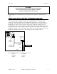
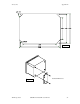
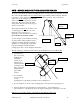
SONDE CABLE CONNECTIONS (SDI-12 COMMUNICATIONS LINK)
In remote Breakout Box installations, Figure 17, the 6500 Monitor uses a standard MS-8
connection to interface with the 6 ft (1.8 m) 6507 Patch Cable that is connected in the 6508
Junction Box. The Junction Box is then connected by conduit and three- conductor cable to the
Breakout Box(s). The customer is advised to supply rigid conduit and 18 AWG or heavier
shielded multi-conductor cable to connect between the Junction Box and the Breakout Box at the
Sonde installation site. This configuration allows a maximum cable length of 250’ between the
6500 Monitor and the sonde(s). The cable from the Junction Box should be landed to TB-1 in the
breakout box. The MS-8 connector for sonde hookup is pre-wired to TB-2 or TB-3.
Enter
Esc
Cal
6500
6500
ENVIR ON MEN TALENVIR ON MEN TAL
MONITORING
MONITORING
SYSTEM
SYSTEM
21.2 Temp
7.35 DO
6.53 pH
Junction Box
6508
Sonde cables
w/ MS-8
Stream
Sondes
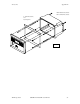
Breakout Box
Conduit &
6507
6’ Patch cable
w/ MS-8
customer-supplied
3-conductor cable
Figure 17
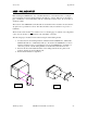
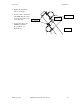
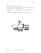
The Junction Box, Figure 17, conductor color code is:
(1) Red +12 VDC
(2) Black Common
(3) Blue SDI-12
YSI Incorporated 6500 Environmental Process Monitor 88