
User Manual

Accessories Appendix D
Enter
Esc
Cal
6500
6500
ENVI RON M EN TALENVI RON M EN TAL
MONITORING
MONITORING
SYSTEM
SYSTEM
21.2 Temp
7.35 DO
6.53 pH
6507
6’ Patch cable
w/ MS-8
Sonde cables
w/ MS-8
Stream
Sondes
6504
Breakout Box
6507
Gland Fitting
Enter
Esc
Cal
6500
6500
ENVIR ON MEN TALENVIR ON MEN TAL
MONITORING
MONITORING
SYSTEM
SYSTEM
21.2 Temp
7.35 DO
6.53 pH
Junction Box
6508
Sonde cables
w/ MS-8
Stream
Sondes
Breakout Box
Conduit &
6507
6’ Patch cable
w/ MS-8
customer-supplied
3-conductor cable
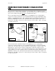
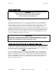
In remote Breakout Box installations, Figure 4, the 6500 Monitor uses a standard MS-8
connection to interface with the 6 foot (1.8 m) 6507 Patch Cable that is connected in the 6508
Junction Box. The Junction Box is then connected by conduit and three- conductor cable to the
Breakout Box(s). The customer is advised to supply rigid conduit and 18 AWG or heavier
shielded multi-conductor cable to connect between the Junction Box and the Breakout Box at the
Sonde installation site. This configuration allows a maximum cable length of 250’ between the
6500 Monitor and the Sonde(s). The cable from the junction box should be landed to TB-1 in the
breakout box. The MS-8 connectors for Sonde hookups are pre-wired to TB-2 and TB-3. See
Figure 12 for further information.
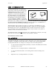
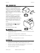
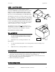
6504, Front Cover Removed
(
2
)
MS-8 to Sonde
3/4” conduit to Jct. Box
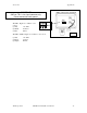
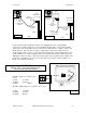
The TB-1, Figure 12, conductor color
code is:
(1) Red +12 VDC
(2) Black Common
(3) Blue SDI-12
IMPORTANT!
GND on TB-1 is for signal common only.
Do not connect to earth ground.
132
TB-1
Figure 11
Figure 10
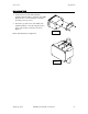
The TB-2 & TB-3, Figure 12, conductor color code is:
(1) Red +12 VDC
Figure12
(2) Black Common
(3) Purple SDI-12
YSI Incorporated 6500 Environmental Process Monitor 84