YSI i n c o r p o r a t e d YSI MODEL 6500 Environmental Process Monitor Operations Manual
CONTENTS Section 1 INTRODUCTION 1.1 6500 Monitor Features 1.2 How to Use This Manual Page 1 1 2 Section 2 INSTALLATION 2.1 Unpacking and Inspection 2.2 Selecting an Installation Location 2.3 Installing the Sonde 2.4 Installing the 6500 Monitor 2.5 Wiring Instructions 2.5.1 Sonde Connections 2.5.2 AC Power Connections 2.5.3 Relays and Output Wiring 2.5.4 Grounding Information 2.5.5 Safety Issues 2.5.6 Lightning and Surge Protection 2.6 Sealants, Desiccant and Securing the Monitor 2.
Section 6 TROUBLESHOOTING 6.1 Communication Problems 6.2 6500 Menu Choice Problems 6.3 Calibration Error Messages 6.4 Sensor Accuracy and Repeatability Problems 6.5 Alarm Function Problems 6.
SECTION 1 INTRODUCTION The 6500 Environmental Process Monitor is designed for configuration with YSI 6-Series sonde(s) to measure up to fifteen water quality parameters. All sensors that perform the parameter measurements are located on the 6-Series sonde, which is submersed and secured in the medium. Conversion of the sensor signals from analog to digital is performed by microprocessor based electronics located in the 6-Series sonde interior.
Introduction Section 1 With the optional Breakout Box (YSI #6504), the 6500 Environmental Process Monitor can be used with multiple sondes. The 6500 Monitor is designed for indoor or outdoor use, and features a watertight enclosure. An optional weather shield (YSI # 6505) is also available. Other optional accessories include several different mounting kits for the sondes and 6500 Monitor. See Appendix D, Accessories, for more information. 1.
SECTION 2 INSTALLATION 2.1 UNPACKING AND INSPECTION Inspect the outside of the shipping carton for damage. If damage is detected, contact the carrier immediately. Remove the instrument from the shipping container. Be careful not to discard any parts or supplies. Confirm that all items on the packing list are present. Inspect all assemblies and components for damage. The basic 6500 Environmental Process Monitor is shipped with the following major components.
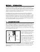
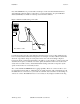
Installation Section 2 Two major components make up the 6500 Environmental Monitoring System: the 6500 Monitor and the 6-Series Sonde that contains the sensors. The sonde is a multi-parameter sensor device that must be placed in a representative sampling location to monitor desired water quality parameters in the flow stream.
Installation Section 2 Figure 1 Sonde orientation Not drawn to scale. Sonde Stream If the sonde is to be utilized in monitoring for results of chemical feeds and resulting chemical reactions, sufficient downstream mixing and reaction time should be provided prior to insertion of the sonde for monitoring. If pH adjustment is necessary, the sonde location should provide for sufficient mixing and reaction time upstream of the location.
Installation Section 2 Note: The 6500 Monitor is provided with a weatherproof enclosure that will withstand most environmental conditions with no compromise to system performance. An optional Weather Shield (YSI #6505) is available for added protection from the elements. Figure 2 Monitor installed using sonde cable 6500 Monitor 6500 EN VIRO N MEN TAL MO N ITO RIN G SYSTEM 21.2 Temp 7.35 DO 6.53 pH Esc Cal Enter AC Sonde Not drawn to scale.
Installation Section 2 Figure 3 Remote location of monitor relative to sonde 6500 Monitor 6500 EN VIRON MEN TAL MO N ITORIN G S YS TEM 21.2 Temp 7.35 DO 6.53 pH Esc Cal 6508 Junction Box Enter Breakout Box AC 6507 6’ Patch cable w/ MS-8 sonde cable w/ MS-8 Conduit & customer-supplied 3-conductor cable 250’ Maximum Sonde Not drawn to scale. Stream YSI also provides a means for convenient and accurate bench calibration of the sonde. Refer to the Sonde Manual for bench calibration procedures.
Installation Section 2 RAIL MOUNT OPTION The sonde can be mounted in a number of different configurations, but a rail mount with a fabricated bracket is recommended. A rail mount kit is also available from YSI, #6511 for 600 series sondes, and 6512 for 6820/6920 sondes. See Appendix D, Accessories for more information. Figures 4 and 5 show the two common connection layouts and short and long-range wiring of the monitor to the sonde.
Installation Section 2 Figure 5 Sonde installed distant from the 6500 Monitor 6500 EN ENVIRON VIRONMEN MEN TAL TAL MON MONITORIN ITORING G SYSTEM SYSTEM SCADA 21.2 Temp 7.35 DO 6.53 pH 6508 Esc Cal Enter 4-20 mA out Relay output AC power in Alarms Junction Box conduit Breakout 6507 6’ Patch cable w/ MS-8 up to 250 ‘ customer-supplied 3-conductor cable sonde cable w/ MS-8 Sonde Stream 2.4 INSTALLING THE 6500 MONITOR The 6500 Monitor should be located within 250-ft (75 m) of the sonde.
Installation Section 2 Figure 6 Attaching the Mounting Brackets The following steps should be followed when wall mounting the 6500 Monitor. 1. Loosely fasten the mounting brackets (included) to the back of the 6500 Monitor with the mounting screws provided as shown in Figure 6. 2. Tighten the screws, securing the brackets to the Monitor. 3. Loosely fasten the 6500 Monitor to the mounting surface with the mounting screws provided as shown in Figure 7. 4.
Installation Section 2 WARNING! A qualified electrician should perform wiring. Do not make connections while power is applied. Disconnect power before proceeding. This particular phase of the installation will vary considerably depending on the distance between the sonde and monitor and on which outputs you use in your particular configuration.
Installation Section 2 The 6507 Patch Cable is pre-wired. The conductor color code is: Red +12 VDC Black Common Purple SDI-12 SDI-12 GND +12 VDC 6502, Front Cover Removed TB-1 1 2 Figure 8 Connector TB-1 detail 3 MS-8 to sonde 3/4” conduit to jct box 6508 6500 EN VIRON MEN TAL MON ITORIN G SYSTEM 21.2 Temp 7.35 DO 6.
Installation Section 2 2.5.2 AC POWER INPUT WIRING The 6500 Monitor has a switching power supply and can operate on 100 to 240 VAC power. When you remove the front panel of the 6500 Monitor, take care not to drop the cover since it is not hinged to the Monitor. Refer to figure 8 for power installation. Connect AC power to TB1-1, L1 and L2. Connect ground wire to one of the three 10-32 grounding screws using a lug (not provided).
Installation Section 2 Use the following precautions from UL 508 as a guide to safety for personnel and property. ¾ AC connections and grounding must be in compliance with UL 508 and/or local electrical codes. ¾ The metal stiffener provides support and proper electrical continuity between conduit fittings. ¾ This type 4/4X enclosure requires a conduit hub or equivalent that provides watertight connection, REF UL 508-26.10.
Installation Section 2 2.5.4 GROUNDING INFORMATION This section contains important installation information regarding grounding of the 6500 Monitor and 6-Series Sonde. The sonde is powered by the 6500 Monitor or by batteries (depending on which sonde you have chosen) and will be operated with a “floating” ground reference. This requires that the sonde not be individually grounded. Grounding the sonde individually will cause a “ground loop”; i.e.
Installation Section 2 mode suppression and nanosecond reaction time. Surge suppressors should be internally fused to remove the load if the unit is overloaded or the internal protection fails. Signal line suppressors protect 4-20 mA DC current loops, low voltage signals and relay outputs from damage due to electrical transients induced in the signal lines from lightning discharges or nearby electrical devices. Signal line suppressors should be installed at each end of an analog loop.
Installation Section 2 channel before inserting the screws. When securing the screws, take care not to cross thread. The screws are stainless steel, and the receiving threads are brass. Do not over-tighten! IMPORTANT! Anytime the 6500 cover is removed, replace the desiccant packs with new packs. Anytime the 6500 front panel is removed, place it on top of the 6500 Monitor or secure it so that the blue ribbon cable does not bear the weight of the cover. 2.
Installation YSI Incorporated Section 2 6500 Environmental Process Monitor 18
SECTION 3 SYSTEM SETUP This section is designed to quickly familiarize you with the hardware and software components of the 6500 Monitor, the 6-Series Sonde and the overall system. You will learn about cable connections and basic communication between the 6-Series Sonde and the 6500 Monitor. Diagrams, menu flow charts and basic written instructions will guide you through basic hardware and software setup.
System Setup Section 3 Sonde to 6500 Monitor 6500 EN ENVIRON VIRO NMEN MEN TAL TAL MON MONITORIN ITORIN G SYSTEM SYSTE M 21.2 Temp 7.35 DO 6.53 pH Esc Cal Enter MS-8 AC power in 4-20 mA out Relay output You will need... 60 0 Sonde 3.2 T T T T Sonde and cable 6500 Monitor AC Power Mounting Hardware 6-SERIES SONDE SETUP The 6-Series Sonde contains a powerful computer that allows the sonde to be configured for use with the 6500 Monitor.
System Setup Section 3 6500 Monitor, a “YSI” display will momentarily appear on the 6500 screen followed by display of actual parameter readings. 6500 ENVIRONMENTAL MONITORING SYSTEM 21.2 Temp 7.35 DO 6.53 pH Esc Cal Enter Multiple sondes may be attached to the 6500 Monitor using the optional 6504 Breakout Box. See Appendix D, Accessories, for more details. Setup of both the sonde and monitor is achieved through use of the Main menu associated with the 6500 software.
System Setup Section 3 SENSOR The first step that should be taken in setting up the sonde is to enable the proper sensors. This is accomplished by highlighting the Sensor selection and pressing Enter. The following display will appear. The Sensor Menu allows the user to enable or disable any of the available sensors. Selected sensors have a check mark next to them. Using the ↑↓ arrows to highlight items, the Enter key will toggle selections on and off.
System Setup Section 3 In the above example, the temperature parameter has been selected. The user can select a displayed unit using the ↑↓ arrows to highlight. If the user selects NONE, the temperature parameter will not appear in the report. When the desired selection has been made, press enter to activate the change. In this example, temperature in degrees Celsius has been designated for display and will appear on the display when the 6500 Monitor is in the Run mode.
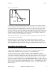
System Setup Section 3 3.3.1 CALIBRATION SETUP Highlight the Calibration setup selection and press Enter. The following screen will be displayed. The Calibration Setup submenu presents two items: (1) Calibrations enabled is a list of all possible sensor calibrations that can either be enabled or disabled with regard to calibration from the Run mode.
System Setup Section 3 Next highlight the Advanced setup selection, press Enter, and a display similar to the following for specific conductance will appear. You need to consider four options within this menu. Is: Enabled. This determines whether or not the calibration of this parameter is enabled (allowed) from the Run mode of the 6500 display. Highlight the selection “Is: Enabled”. Press Enter to toggle back and forth between “Is: Enable” and “Is: Disabled”. Select the desired option.
System Setup 3.3.2 Section 3 DISPLAY SETUP Now highlight the Display selection from the Main menu and press Enter. The following screen will appear. The Display menu contains options concerning the visual display of the 6500 Monitor. Use the ↑↓ arrows to highlight the desired display feature. Press Enter to select the feature. First, highlight the Adjust contrast selection. This option allows the user to select the optimal screen contrast for the existing light conditions.
System Setup Section 3 at the bottom of the screen with symbols that indicate whether the relays are presently active as defined by the current sensor value. An example is shown in the following Run screen. If a relay is active, the symbol will be spinning as is simulated above for relays 2 and 4. If the relay is inactive, the symbols will be stationary as shown above for relays 1 and 3.
System Setup Section 3 If you are using more than one sonde with your 6500 Monitor, you can choose how many sondes you would like to view on the 6500 Monitor screen simultaneously by selecting the Multi-sonde option as shown below. Once selected, two additional options appear as shown. You will now want to select the number of lines (displayed parameters) which will be shown simultaneously on the 6500 Monitor during the run mode. Highlight Lines per Sonde and press Enter.
System Setup 3.3.3 Section 3 RELAYS If you do not choose to use the 6500 Relay function, proceed to the next section, 3.3.4 4-20 mA channel set-up. Highlight the Relays option, press Enter and the following display will appear. The Relays menu allows the user to set up the logic and levels for turning the four available relays on and off. If a relay is active, it might trigger an alarm indicating a problem in the stream.
System Setup Section 3 Now highlight the “Is:” selection and use the Enter key to toggle between “above” and “below”. When the proper selection has been made, press Enter to confirm it (“above” in the example”). Next highlight the “Set point=“ selection and press Enter. Use the up and down arrows on the keyboard to adjust the parameter value to the point where the relay will be activated (18 C in the example) and press Enter to confirm the selection.
System Setup Section 3 If you do not choose to use the 6500 4-20 mA function, proceed to the next section. To enter the 4-20 menu press Enter after highlighting “4-20 mA”, then choose “Configure 4-20mA” and press Enter again. If you will be transmitting data from the sonde via your 6500 to a SCADA system or other analog data collection device in the form of 4-20 mA signals, you will need to set the limits of this output for any or all of the eight available channels.
System Setup Section 3 After the 4-20 mA channels have been configured to your specifications, press Esc to return to the Main menu. 3.3.5 MODBUS SETUP Please see section 5.1 for a more complete description of the Modbus system implementation. To begin setup of the Modbus, highlight the Modbus setup option on the Main menu and press Enter. The following screen will appear. Use the arrow keys to highlight Base address and press Enter to select it.
System Setup Section 3 Highlight the desired setting and press Enter to select it. All of the listed Modbus parameters must be set to match those specified in your Modbus configuration for successful system implementation. Most parameters have a submenu of available settings. Change any other necessary Modbus settings in the same fashion. After your have configured the Modbus setup as desired, check the “Enable Modbus” option to activate the Modbus system by pressing Enter.
System Setup Section 3 To change an SDI-12 addresses, highlight the current SDI-12 address of the sonde you wish to change and press Enter to select it. A new screen showing available new addresses will be displayed. Choose the desired address and press Enter to select it. The 6500 Monitor will then display a confirmation choice verify that your selection was correct. The current active choice will flash. Verify your choice is correct and use the arrow keys to highlight “yes” or “no”.
System Setup Section 3 Note that the current software version and date are shown in the first entry. This information will be useful when contacting authorized service personnel for advice on the capabilities of your system. The second entry in the System status menu is “Wiper Interval”. If your sonde is equipped with a YSI #6026 turbidity sensor, highlight the Wiper Interval, press enter, and use the arrow keys to set the number of minutes between wiper activation cycles.
SECTION 4 CALIBRATION In this section, you will learn how to calibrate the 6-Series Sonde sensors using the 6500 Monitor (field calibration) as the interface device. You will also learn how to view your data on a computer display. MULTIPLE SONDE CALIBRATION If you are using multiple sondes with the 6500 Monitor, each sonde must be calibrated separately. To calibrate each sonde, first make sure that the name of the sonde is highlighted, as in the figure below.
Laboratory and Field Calibration Section 4 CONTAINERS NEEDED TO CALIBRATE A SONDE The calibration cup that comes with your sonde serves as a calibration chamber for all calibrations. You need to visually observe the turbidity calibration to insure that no air bubbles are trapped near the optics and that standards are homogeneous. If you are using the 6026 “wiping” turbidity probe, you should visually verify proper movement of the wiper mechanism.
Laboratory and Field Calibration Section 4 6. You do not need to remove the probe guard to rinse and dry the probes between calibration solutions. The inaccuracy resulting from simply rinsing the probe compartment and drying the outside of the sonde is minimal. 7. For the 600R, 600XL and 600XLM, remove the stainless steel weight from the bottom of the sonde by turning the weight counterclockwise.
Laboratory and Field Calibration Section 4 6820 and 6920 Sondes Upright Upside Down Conductivity pH/ORP ISE Turbidity 200ml 100ml 125ml 25ml 200ml 250ml 275ml N/A Table 2 600R, 600XL and 600XLM Conductivity pH/ORP Upright 50ml 25ml Upside Down 50ml 50ml 4.2 FIELD CALIBRATION USING THE 6500 MONITOR The 6-Series Sonde can be calibrated in the field using the 6500 Monitor display.
Laboratory and Field Calibration Section 4 Use the arrow keys to highlight the output line for specific conductance as shown above. Press Enter and the following display will be shown. Using this display, you will now be required to input the ACTUAL value of your conductivity standard. First use the right and left keyboard arrow keys to highlight the digits of the display which your wish to vary.
Laboratory and Field Calibration Section 4 Now simply press the Enter key to return to the Calibration display and proceed to calibration of the other sensors using the same basic procedures as described above for specific conductance. 4.3 6500 CALIBRATION WARNING AND ERROR MESSAGES When you calibrate the 6-Series Sonde sensors with the 6500 Monitor, you may occasionally encounter an error message display similar to those shown below when attempting to confirm a calibration value.
SECTION 5 PROPER USE AND CARE OF THE 6500 SYSTEM You are now ready to use your system to monitor the water quality of your stream by simultaneously measuring key parameters such as temperature, dissolved oxygen, conductivity, and pH. Within this section are tips, precautions and protocol for quality assurance. 5.
Proper Use and Care of the 6500 Section 5 IMPLEMENTATION OF MODBUS SYSTEM The 6500 Modbus system can be implemented if your application requires digital data management of one or many parameters on a single data channel. This system involves a simple interface between the 6500 Monitor and a Programmable Logic Controller (PLC). Configuration of the PLC should be done only by programmers and engineers with PLC experience.
Proper Use and Care of the 6500 Section 5 The following table shows the register areas defined in the 6500: Address 1-128 129-143 Read/Write Read/Write 144-256 257-271 Read only 272-384 385-414 Read only 415-640 YSI Incorporated Description Unused Parameter type The PLC must write to this area to tell the 6500 what parameters it wants. Up to 15 parameters can be written here. After the last parameter the PLC must write a “0”.
Proper Use and Care of the 6500 641-655 Read only Section 5 Scaled integer parameter data The PLC should only read data from the 6500 using this method if it cannot handle floating point data. Most PLCs can manipulate floating point values, so you should try to avoid reading scaled integer values. The value in register 641 corresponds to the parameter type in register 129 and so on. The values are scaled according to a fixed table in the 6500. The scaled data is in an unsigned integer format.
Proper Use and Care of the 6500 Section 5 MODBUS SETUP MENU This menu is accessed from the main menu under “Modbus setup”. Menu item Enable Modbus Address Hardware Format Baud rate Data bits Stop bits Parity Valid Messages Param peek Item description This item must be “checked” to enable Modbus. Note: this item must be off in order to update the code on a 6500. The effective Modbus address is the value you set here plus the sonde address.
Proper Use and Care of the 6500 Section 5 The following sections are designed to help you in these important areas by providing maintenance tips for the overall sonde deployment, help in implementing a quality assurance protocol, and suggested service methods and intervals for the sonde sensors. 5.2.
Proper Use and Care of the 6500 Section 5 The sensors associated with the 6-Series Sonde are of high quality and should exhibit excellent performance in your application in excess of the warranty period. However, the dissolved oxygen, pH, and conductivity sensors will inevitably show some drift during deployment due to natural chemical changes to the reagents in the probes, physical changes of the electrodes, minor fouling of the sensor surfaces, or all of these factors.
Proper Use and Care of the 6500 Section 5 7. Replace the sonde guard. 8. Place the sonde in enough pH 7 buffer to immerse the pH probes. Wait about 3 minutes for the sensor to stabilize in the new medium and record the reading shown on the 6500 Monitor display. The deviation from pH 7 will reflect the sensor drift during the deployment period. 9.
Proper Use and Care of the 6500 Section 5 shown on the 6500 display with those taken by recently-calibrated single parameter instruments. For dissolved oxygen, the probe of a handheld DO instrument similar to the YSI Model 55 can be placed in the stream near the 6-Series Sonde and the reading recorded.
Proper Use and Care of the 6500 5.2.5 Section 5 RECOMMENDED CLEANING OF THE 6500 MONITOR AND ACCESSORIES Clean the 6500 Monitor and accessories as needed. Dampen a cloth with warm water and wipe the outside of the unit. You may use mild detergent with water, if necessary. Do not use acid-based, alkali-based or organic solvent-based solvents (e.g., acetone, alcohol, etc.).
SECTION 6 TROUBLESHOOTING The following section is designed to identify and correct the most common problems that you might encounter when using your 6500/6-Series system in a stream.
Troubleshooting Section 6 front cover and reapply AC power to the unit. If a display still does not appear, turn off the power and consult authorized service for advice. Symptom: No sensor display appears when the 6-Series Sonde is connected to the 6500 Monitor -- only the message “No sonde on line” is present at the bottom of the screen. Possible Cause and Suggested Action: The sonde communication software may not be configured correctly.
Troubleshooting Section 6 unique address. A conflicting address will cause the described communication errors between the 6500 monitor and the conflicting sondes. This problem is characterized by repeated alarm sounds and loss of 6500 Monitor functionality. If this error condition occurs, disconnect all sondes from the 6500 Monitor and proceed as outlined below. It is possible to remedy this problem by changing a conflicting SDI-12 addresss.
Troubleshooting Section 6 6.3 CALIBRATION ERROR MESSAGES Symptom: When attempting to confirm a dissolved oxygen sensor calibration, an error message appears which indicates “High DO Charge”. Possible Cause and Suggested Action: This message indicates a malfunction in the DO sensor that is generally due to the roughness of the electrodes on the surface of the probe face. The charge associated with the DO sensor must be in the range 25 to 100 or the error message will appear when calibration is attempted.
Troubleshooting Section 6 Possible Cause and Suggested Action: The individual pH and conductivity sensors (not just the sonde guard) may have been extensively fouled with debris. Remove the sonde from the stream. Clean the pH glass and reference electrodes by carefully wiping with moist lens cleaning tissue and then rinse with clean water. Clean out the conductivity sensor ports with the brush supplied with the 6-Series Sonde and then rinse with clean water. Inspect the dissolved oxygen probe face.
Troubleshooting Section 6 6.6 4-20 MA CURRENT LOOP OUTPUT PROBLEMS Symptom: 4-20 mA output values at the SCADA or recorder are suspicious or inconsistent with the scale you have set in the 6500 setup menu. Possible Cause and Suggested Action: The problem may be related to the 6500 circuitry, the wiring and/or the SCADA controller. Use the diagnostics menu in the 6500 Monitor to check the outputs of the 4-20 mA outputs. Start checking at the SCADA and work back to the 6500 Monitor.
SECTION 7 WARRANTY AND SERVICE INFORMATION The YSI 6500 Environmental Process Monitor and 6502/6503 Breakout Boxes are warranted for two years from date of purchase by the end user against defects in materials and workmanship. All cables are warranted for one year from date of purchase by the end user against defects in material and workmanship. The warranty period for chemicals and reagents is determined by the expiration date printed on their labels.
Warranty and Service Information Section 7 AUTHORIZED SERVICE CENTERS Please visit www.ysi.com or contact YSI Technical Support for the nearest authorized service center. YSI Incorporated • Technical Support • Phone: +1 937 767-7241 • 800 897-4151 • Fax: 937 767-1058 • Email: environmental@ysi.
Warranty and Service Information YSI Incorporated Environmental Monitoring Systems Operations Manual Section 7 61
Warranty and Service Information YSI Incorporated Environmental Monitoring Systems Operations Manual Section 7 62
APPENDIX A SPECIFICATIONS 6500 Environmental Process Monitor Operating Temperature -20 to 60 oC or -4 to 140 oF Enclosure Rating* NEMA 4X enclosure Line Power (nominal) 100 (-10%) to 240 (+10%) VAC, 50-60 Hz Maximum Power Draw 45 watts Control relay outputs Rated 5 Amps @ 240 VAC 4 - 20 mA loops Class L, 0 to 300 ohms (250 ohm typical) 4 - 20 mA output accuracy +/- 0.08 mA (electrically isolated from sensors.
Specifications YSI Incorporated Appendix A 6500 Environmental Process Monitor 64
APPENDIX B HEALTH AND SAFETY YSI Conductivity solutions: 3161, 3163, 3165, 3167, 3168, 3169 INGREDIENTS: T Iodine T Potassium Chloride T Water WARNING: INHALATION MAY BE FATAL. CAUTION: AVOID INHALATION, SKIN CONTACT, EYE CONTACT OR INGESTION. MAY EVOLVE TOXIC FUMES IN FIRE. Harmful if ingested or inhaled. Skin or eye contact may cause irritation. Has a corrosive effect on the gastro-intestinal tract, causing abdominal pain, vomiting, and diarrhea.
Health and Safety Appendix B YSI pH 4.00, 7.00, and 10.00 Buffer Solutions: 3821, 3822, 3823 pH 4 INGREDIENTS: T Potassium Hydrogen Phthalate T Formaldehyde T Water pH 7 INGREDIENTS: T Sodium Phosphate, Dibasic T Potassium Phosphate, Monobasic T Water pH 10 INGREDIENTS: T Potassium Borate, Tetra T Potassium Carbonate T Potassium Hydroxide T Sodium (di) Ethylenediamine Tetraacetate T Water CAUTION - AVOID INHALATION, SKIN CONTACT, EYE CONTACT OR INGESTION. MAY AFFECT MUCOUS MEMBRANES.
Health and Safety Appendix B YSI Zobell Solution: 3682 INGREDIENTS: T Potassium Chloride T Potassium Ferrocyanide Trihydrate T Potassium Ferricyanide CAUTION - AVOID INHALATION, SKIN CONTACT, EYE CONTACT OR INGESTION. MAY AFFECT MUCOUS MEMBRANES. May be harmful by inhalation, ingestion, or skin absorption. Causes eye and skin irritation. Material is irritating to mucous membranes and upper respiratory tract. The chemical, physical, and toxicological properties have not been thoroughly investigated.
Health and Safety Appendix B YSI Ammonium Standard Solutions: 3841, 3842, and 3843 INGREDIENTS: T Ammonium Chloride T Lithium Acetate Dihydrate T Sodium Azide (trace) T Hydrochloric acid CAUTION - AVOID INHALATION, SKIN CONTACT, EYE CONTACT OR INGESTION. MAY AFFECT MUCOUS MEMBRANES. May be harmful by ingestion or skin absorption. May cause eye and skin irritation. The chemical, physical, and toxicological properties have not been thoroughly investigated.
Health and Safety Appendix B YSI Nitrate Standard Solutions: 3885, 3886, and 3887 INGREDIENTS T Potassium Nitrate T Magnesium Sulfate T Gentamycin Sulfate (Trace) CAUTION - AVOID INHALATION, SKIN CONTACT, EYE CONTACT OR INGESTION. May be harmful by ingestion or skin absorption. May cause eye and skin irritation. The chemical, physical, and toxicological properties have not been thoroughly investigated. FIRST AID: INHALATION - Remove to fresh air. If not breathing, give artificial respiration.
Health and Safety Appendix B YSI Turbidity Standards: 3845, 3846, 3487, 6072, and 6073 INGREDIENTS T Styrene divinylbenzene copolymer spheres The material is not volatile and has no known ill effects on skin, eyes, or on ingestion. Therefore, no special precautions are required when using the standards. General precautions should be adopted as required with all materials to minimize unnecessary contact.
Health and Safety Appendix B YSI Replacement Desiccant 065802 INGREDIENTS T Calcium Sulfate and Calcium Chloride CAUTION - AVOID INHALATION, SKIN CONTACT, EYE CONTACT OR INGESTION. MAY AFFECT MUCOUS MEMBRANES. FIRST AID: SKIN CONTACT - Flush with water. EYE CONTACT - . Flush with water. If irritation continues, obtain medical attention. INGESTION - If patient is conscious, induce vomiting. Obtain medical attention.
Health and Safety YSI Incorporated Appendix B 6500 Environmental Process Monitor 72
APPENDIX C REQUIRED NOTICE The Federal Communications Commission defines this product as a computing device and requires the following notice. This equipment generates and uses radio frequency energy and if not installed and used properly, may cause interference to radio and television reception.
Required Notice YSI Incorporated Appendix C 6500 Environmental Process Monitor 74
APPENDIX D ACCESSORIES The following components come standard with the purchase of the YSI 6500 Environmental Monitoring System: ¾ ¾ ¾ ¾ ¾ ¾ ¾ 6500 Monitor Mounting Flange Kit 6506 Desiccant Kit 065921 Industrial Encapsulant (conduit sealer cartridge) 065926 Conduit Fittings (3) 065927 Knockout Plugs (2) 065902 Instruction Manual ¾ 065979 Field Operation Guide OPTIONAL ACCESSORIES FOR 6500 MONITOR ♦ 6502 Breakout Box – for one sonde up to 250 feet away from the 6500 Monitor ♦ 6503 CE Breakout Box – f
Accessories Appendix D 6502 – BREAKOUT BOX Figure 1 The 6502 Breakout Box is required when deploying the sonde longer than the field cable length from the monitor. The Breakout Box has one MS-8 connector for connection to the sonde cable and one conduit fitting for connection with the YSI #6508 Junction Box. For direct connection to the 6500 Monitor, a #6507 Patch Cable and Gland Fitting (YSI 064007) are required.
Accessories Appendix D RAIL MOUNTING 1. Securely fasten both mounting brackets (included with the 6502) to the back of the 6502 Breakout Box, with the mounting screws provided. 2. Fasten the top and bottom of the 6502, with installed brackets, to the rail using the u-bolts, plates, lock-washers, and nuts. 3. Ensure that all hardware is tightened. WIRING INSTRUCTIONS WARNING! A qualified electrician should perform all Wiring. Do not make connections while power is applied.
Accessories Appendix D SONDE CABLE CONNECTIONS (SDI-12 COMMUNICATIONS LINK) The sonde can be equipped with a detachable or non-detachable cable or a bulkhead connector that allows the use of various YSI field cables. The end connection of the cable is a military-style 8-pin connector (MS-8) that plugs directly into the 6502 Breakout Box. In close range Breakout Box installations, Figure 2, the 6500 Monitor uses a standard MS-8 connection to interface with the 6 foot (1.
Accessories Appendix D 6502, Front Cover Removed IMPORTANT! GND on TB-1 is for signal common only. Do not connect to earth ground. The TB-1, Figure 4, conductor color code is: (1) Red +12 VDC (2) Black Common (3) Blue TB-1 1 2 3 SDI-12 (2) MS-8 to Sonde The TB-2 & TB-3, Figure 4, conductor color code is: (1) Red +12 VDC (2) Black Common (3) Purple SDI-12 YSI Incorporated 3/4” conduit to Jct.
Accessories Appendix D 6503 – CE BREAKOUT BOX Figure 5 The 6503 CE Breakout Box is required when deploying the sonde longer than the field cable length from the monitor. If you are using your YSI 6500 with a Breakout Box in a CE applications, you must use the #6503 Breakout Box.
Accessories Appendix D RAIL MOUNTING 1. Securely fasten both mounting brackets (included with the 6502) to the back of the 6502 Breakout Box as shown in Figure 6, with the mounting screws provided. 2. Fasten the top and bottom of the 6502, with installed brackets, to the rail using the u-bolts, plates, lock-washers, and nuts as shown in Figure 7. Ensure that all hardware is tightened.
Accessories Appendix D 6504 – BREAKOUT BOX The 6504 Breakout Box is required when deploying more than one sonde from the 6500 Monitor (see Figures 8 & 9). The Breakout Box has two MS-8 connectors for connection to the sonde cables and one conduit fitting for connection with the YSI #6508 Junction Box. For direct connection to the 6500 Monitor, a #6507 Patch Cable and Gland Fitting (YSI 064007) are required.
Accessories Appendix D WIRING INSTRUCTIONS WARNING! Wiring should be performed by a qualified electrician. Do not make connections while power is applied. Disconnect power before proceeding. IMPORTANT! It is essential that all sensor wiring be run in a separate conduit from power wiring. The simplest configuration is where the sondes are within 250-feet (75 m) of the 6500 Monitor, the Breakout Box is within 6-ft (1.
Accessories 6500 EN VIRON MEN TAL MON ITORIN G SYSTEM Appendix D 6500 21.2 Temp 7.35 DO 6.53 pH EN VIRON MEN TAL MON ITORIN G SYSTEM 21.2 Temp 7.35 DO 6.
Accessories Appendix D 6505 – WEATHER SHIELD The Weather Shield provides wall or optional rail mounting capability for the 6500 Monitor using the holes as indicated in Figure 13. Do not mount on electrical conduit. The location of the 6500 Monitor should be elevated and in a dry place above potential flood level. The unit should be easily accessible for an operator or technician.
Accessories Appendix D Figure 14 YSI Incorporated 6500 Environmental Process Monitor 86
Accessories Appendix D 6508 – JUNCTION BOX The 6508 Junction Box is required when the distance between the 6500 Monitor and the Breakout Box(s) is more than 6-feet (1.8 m). The Breakout Box has two conduit fittings, one for the conduit connection with the Breakout Box and one for the Gland Fitting for the 6507 Patch Cable. The 6508 may be mounted on a wall or mounted to vertical pipe or handrail (1 to 1½ inches in diameter).
Accessories Appendix D WARNING! Wiring should be performed by a qualified electrician. Do not make connections while power is applied. Disconnect power before proceeding. IMPORTANT! It is essential that all sensor wiring be run in a separate conduit from power wiring. SONDE CABLE CONNECTIONS (SDI-12 COMMUNICATIONS LINK) In remote Breakout Box installations, Figure 17, the 6500 Monitor uses a standard MS-8 connection to interface with the 6 ft (1.
Accessories Appendix D 6509 – RAIL MOUNT KIT Rail mounting the 6500 Monitor, any of the Breakout Boxes or the Junction Box is a simple process using the enclosed mounting hardware in addition to u-bolts. They may be mounted to pipe or handrail (1 to 1½ inch diameter) with two additional 1½ inch U-bolts. Do not mount on electrical conduit. The location of the 6500 Monitor, Breakout Boxes and Junction Box should be elevated and in a dry place above potential flood level.
Accessories Appendix D Figure 20 YSI Incorporated 6500 Environmental Process Monitor 90
Accessories Appendix D 6510 – PANEL MOUNT KIT Panel mounting the 6500 Monitor is a simple process using the enclosed mounting hardware and the following tools; 5/32” Allen wrench, Philips screwdriver, and the necessary tools for cutting the mounting hole in the control panel. The 6500 Monitor may be mounted in any panel with 9.5”L x 7.5”W space available, and behind the panel depth of 5.5”. The location of the 6500 Monitor should be elevated and in a dry place above potential flood level.
Accessories Appendix D Figure 21 Figure 22 YSI Incorporated 6500 Environmental Process Monitor Countersink Screws 92
Accessories Appendix D Allen Head Screws(8each) and Lock Washers (8each) 4” Standoffs (4each) and Nylon Spacers Figure 23 YSI Incorporated 6500 Environmental Process Monitor 93
Accessories Appendix D 6511 – SONDE MOUNT KIT FOR 6OO SERIES SONDES The 6511 Sonde Mount Kit enables a 600 Series Sonde to be deployed in a permanently mounted two-inch schedule 40 PVC tube, which is not included in kit, approximately 10 feet in length. The tube is mounted to 1-1½” diameter railing by included brackets and uSchedule bolts. The sonde will be deployed by gently 40 PVC sliding it down the tube, where it will rest on a stop cap at the end of the tube.
Accessories Appendix D 6. Tighten all remaining ubolts to secure pipe. 7. Connect cable to the Sonde and slowly slide the Sonde down the pipe until it rests on the Stop Cap. 1.5” U-Bolts Mounting Plates 2” U-Bolts 8. Connect the cable to the 6500 Environmental Process Monitor or Breakout box.
Accessories Appendix D 6512 – SONDE MOUNT KIT FOR 6820/6920 SONDES The 6512 Sonde Mount Kit enables a 6820/6920 sonde to be deployed in a permanently mounted three-inch schedule 40 PVC tube, not included in kit, approximately 10 feet in length. The tube is mounted to 1-1½” diameter railing by included brackets and u-bolts. The sonde will be deployed by gently sliding it down the tube where it will rest on a Stop Cap at the end of the tube.
Accessories Appendix D 5. Tighten all remaining u-bolts to secure the pipe. 6. Remove the probe guard and install the sonde adapter, with the groove toward the sonde body as shown in Figure 28, and reinstall the probe guard. 7. Connect the cable to the sonde and slowly slide the sonde down the pipe until it rests on the Stop Cap. 8. Connect the cable to the 6500 Environmental Process Monitor or Breakout box.
Accessories YSI Incorporated Appendix D 6500 Environmental Process Monitor 98
APPENDIX E SOLUBILITY AND PRESSURE/ALTITUDE TABLES Table 1: Solubility of Oxygen (mg/L) in Water Exposed to Water-Saturated Air at 760 mm Hg Pressure. Salinity = Measure of quantity of dissolved salts in water. Chlorinity = Measure of chloride content, by mass, of water. S(0/00) = 1.80655 x Chlorinity (0/00) ) Temp o C Chlorinity 0 Salinity: 0 5.0 ppt 9.0 ppt 10.0 ppt 18.1 ppt 15.0 ppt 27.1 ppt 20.0 ppt 36.1 ppt 25.0 ppt 45.2 ppt 0.0 14.62 13.73 12.89 12.10 11.36 10.66 1.0 14.22 13.36 12.
Solubility and Pressure/Altitude Tables Temp o C Chlorinity 0 Salinity: 0 5.0 ppt 9.0 ppt Appendix E 10.0 ppt 18.1 ppt 15.0 ppt 27.1 ppt 20.0 ppt 36.1 ppt W 25.0 ppt 45.2 ppt W 19.0 9.28 8.79 8.33 7.90 7.48 7.09 20.0 9.09 8.62 8.17 7.75 7.35 6.96 21.0 8.92 8.46 8.02 7.61 7.21 6.84 22.0 8.74 8.30 7.87 7.47 7.09 6.72 23.0 8.58 8.14 7.73 7.34 6.96 6.61 24.0 8.42 7.99 7.59 7.21 6.84 6.50 25.0 8.26 7.85 7.46 7.08 6.72 6.39 26.0 8.11 7.71 7.33 6.
Solubility and Pressure/Altitude Tables Appendix E Table 2: Calibration Values for Various Atmospheric Pressures and Altitudes PRESSURE Inches Hg 30.23 29.92 29.61 29.33 29.02 28.74 28.43 28.11 27.83 27.52 27.24 26.93 26.61 26.34 26.02 25.75 25.43 25.12 24.84 24.53 24.25 23.94 23.62 23.35 23.03 22.76 22.44 22.13 21.85 21.54 21.26 20.94 20.63 20.35 20.04 19.
Solubility and Pressure/Altitude Tables Table 3: Conversion mg/L/ppm Appendix E Factors TO CONVERT FROM for Feet/Meters, TO Celsius/Fahrenheit, EQUATION Feet Meters Multiply by 0.305 Meters Feet Multiply by 3.28 Degrees Celsius Degrees Fahrenheit 5/9×(oF-32) Degrees Fahrenheit Degrees Celsius 9/5×(oC)+32 Milligrams per liter (mg/L) Parts per million (ppm) Multiply by 1 Table 4.
APPENDIX F ADVANCED CALIBRATION SETUP The Calibration Setup submenu of the 6500 Main menu presents two options, both of which are covered in Setup, Section 3.4. The basic function of each is outlined below. (1) Calibrations enabled is a list of all possible sensor calibrations which can either be enabled or disabled with regard to calibration from the Run mode.
Advanced Calibration Setup Appendix F Can override: Yes. This determines whether or not an error message can be overridden if it occurs during the calibration procedure. Highlight the “Can override: Yes” selection. Press Enter to toggle back and forth between “Can override: Yes” and “Can override: No”. Select the desired option.
APPENDIX G INDEX 4 4-20 MA Current Loop Output Problems 4-20 MA Current Loop Output Wiring 58 14 6 6-Series Sonde Setup Sensor Report 6500 Calibration Waning and Error Messages 6500 Menu Choice Problems 6500 Monitor Features 6500 Monitor Setup Calibration Setup Display Setup 4-20 MA Channel Setup Multiple Sonde Setup Relays System Status 6502 Breakout Box Wall Mounting Rail Mounting Wiring Instructions Sonde Cable Connections 6503 Breakout Box Wall Mounting Rail Mounting 6504 Breakout Box Wall Mounting
Index Appendix G A AC Power Input Wiring Accessories Alarm Function Problems Algae and Debris as the Major Problem Alternative Quality Assurance Protocol Authorized US Service Centers 13 75 57 48 51 60 C Calibration Calibration Checks Calibration Error Messages Change Sonde Address Choosing a Monitor Location Choosing a Sonde Location Communication Problems Conductivity Containers needed to Calibrate a Sonde 37 49 56 33 5 4 53 40 38 F Field Calibration Using the 6500 Monitor 40 G General Calibration
Index Appendix G M Minimizing the effect of algae and debris Modbus Implementation Modbus Setup Multiple Sonde Calibration Multiple Sonde Problems Multiple Sonde Setup 48 44 32,47 37 54 28,33 O Optional Accessories for the 6500 Monitor Optional Accessories for 6-Series Sonde 75 75 P Proper Use and Care of the 6500 System 43 Q Quality Assurance 47 R Rail Mount Option Recommended Cleaning of the 6500 Monitor and Accessories Recommended Monthly Maintenance of the DO Probe Recommended Quality Assuranc
Index Appendix G U Unpacking and Inspection 3 W Wall Mounting Option Warranty and Service Information Wiring Instructions YSI Incorporated 6500 Environmental Process Monitor 9 59 11 108
YSI, Incorporated 6500 Environmental Process Monitor 109
1725 Brannum Lane Yellow Springs, Ohio 45387 USA +1 937 767-7241 800 765-4974 (US) FAX (937) 767-9353 E-mail: environmental@YSI.com Website: www.YSI.