
Manual

YSI Incorporated 6500 Field Guide 6
SET AND CHECK RELAYS AND
4-20 CURRENT LOOPS
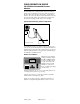
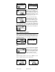
There are 4 relays resident in the 6500
for which parameter limits may be set.
From
Main
menu highlight
Relays
and
press
Enter
. Choose
Configure Relays
in the next screen to display the
Relay,
set, hys
menu shown to the left. For each of the 4 relays press
En-
ter
to activate the next display which
allows you to assign parameter, con-
dition and set point. Note, hysteresis
(hys
) or “dead band” allows you to
manage relay “chatter” at the set
point.
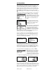
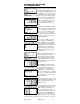
For each relay press
Enter
to activate
the setup screen. For example, Relay 1
is set to close if the temperature rises
above 18
o
C. Use the left and right
arrow keys to move to other relays
and set additional conditions for additional parameters. The display
to the left shows all 4 relays set for 4
different parameters.
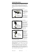
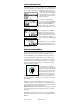
To test relays press
Esc
to
view the
previous screen, then highlight
Test
Relays
and press
Enter
. As shown to the left when you highlight
and press
Enter
, the relay energizes
(you may hear the click) and the relay
icon begins spinning. In addition to
this local relay test, you should also
confirm that the relay signal is prop-
erly transmitted to the alarm or dialing device.
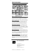
There are eight 4-20 mA current loop
channels resident in the 6500 to
which parameters may be assigned.
From
Main
menu highlight
4-20mA
and press
Enter
. Choose
Configure
4-20mA
in the next screen to display
the 4-20 channels.
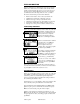
Next highlight a particular channel
and press
Enter
, to view the setup
screen for that channel. See the example for Channel 1 shown to
the left. Choose the parameter by
highlighting
Para, and
then use the
arrow keys and Enter key to assign the
parameter. In a similar manner set the
4 and 20 mA levels for the low and
high temperatures.
Use the left/right arrow keys to assign
additional channels. Press
Esc
to view
a list of all 4-20 channels. See the
display to the left.
To test 4-20 mA current loop outputs return to the 4-20 menu using
Esc
. Highlight
Test 4-20 mA
and press
Enter
. The values for each
channel represent what the sonde
sensors are reading based on the con-
figuration range that was assigned.
Alternatively, press
Enter and
then
use the arrow keys to enter a known
mA value, e.g., 12 mA. This should equal 15
o
C based on the range
assigned. Check your SCADA or recorder for accurate conversion.