
Manual

YSI Incorporated 6500 Field Guide 1
FIELD OPERATION GUIDE
YSI 6500 Environmental Process
Monitor
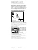
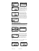
The YSI 6500 monitor combined with the YSI 6-series multi pa-
rameter sondes is intended for use in water quality monitoring ap-
plications. The sondes are able to measure up to 15 different pa-
rameters. The sensors are all located in the submersible sonde that
also contains signal circuitry and communications circuitry that
transmit sensor readings via SDI-12 protocol to the 6500.
Typical 6500 monitoring system configuration
Enter
Esc
Cal
6500
6500
ENVIRONMENTALENVIRONMENTAL
MONITORING
MONITORING
SYSTEMSYSTEM
21.2 Te mp
7.35 DO
6.53 pH
AC
Sonde
Stream
Not drawn to scale.
6500 Monitor
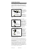
For installing the monitor more than 25’ and up to 250’ from the
sonde, use an optional YSI breakout box and patch cable with user-
supplied wire. For using the monitor with more than one sonde, use
the YSI # 6508 Junction Box. See Appendix D of the 6500 Opera-
tions Manual for installation details.
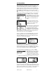
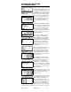
Monitor user interface
In Run mode view parameter
readings from the LC display.
Press
Esc
and
Enter
simulta-
neously to enter
Main
menu
for setup. Press
Cal
to enter
calibration menus for field
calibrations. Use the arrow
keys to scroll through readings
or menu choices.
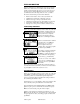
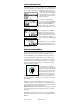
Visually check display for one or more of the multi parameter sen-
sor readings. Record for hard copy reporting.
Configure set points for up to four relays resident in the 6500 to
activate alarms or automatic phone dialer.
Output sensor readings using up to eight 4-20 mA current loop
channels for integration with plant SCADA system or recorder.
Enter
Esc
Cal
6500
6500
ENVIRONMENTAL
ENVIRONMENTAL
MONITORING
MONITORING
SYSTEM
SYSTEM
21.2 Temp
7.35 DO
6.53 pH