
Manual


YSI 5X00
141
YSI 5X00
140
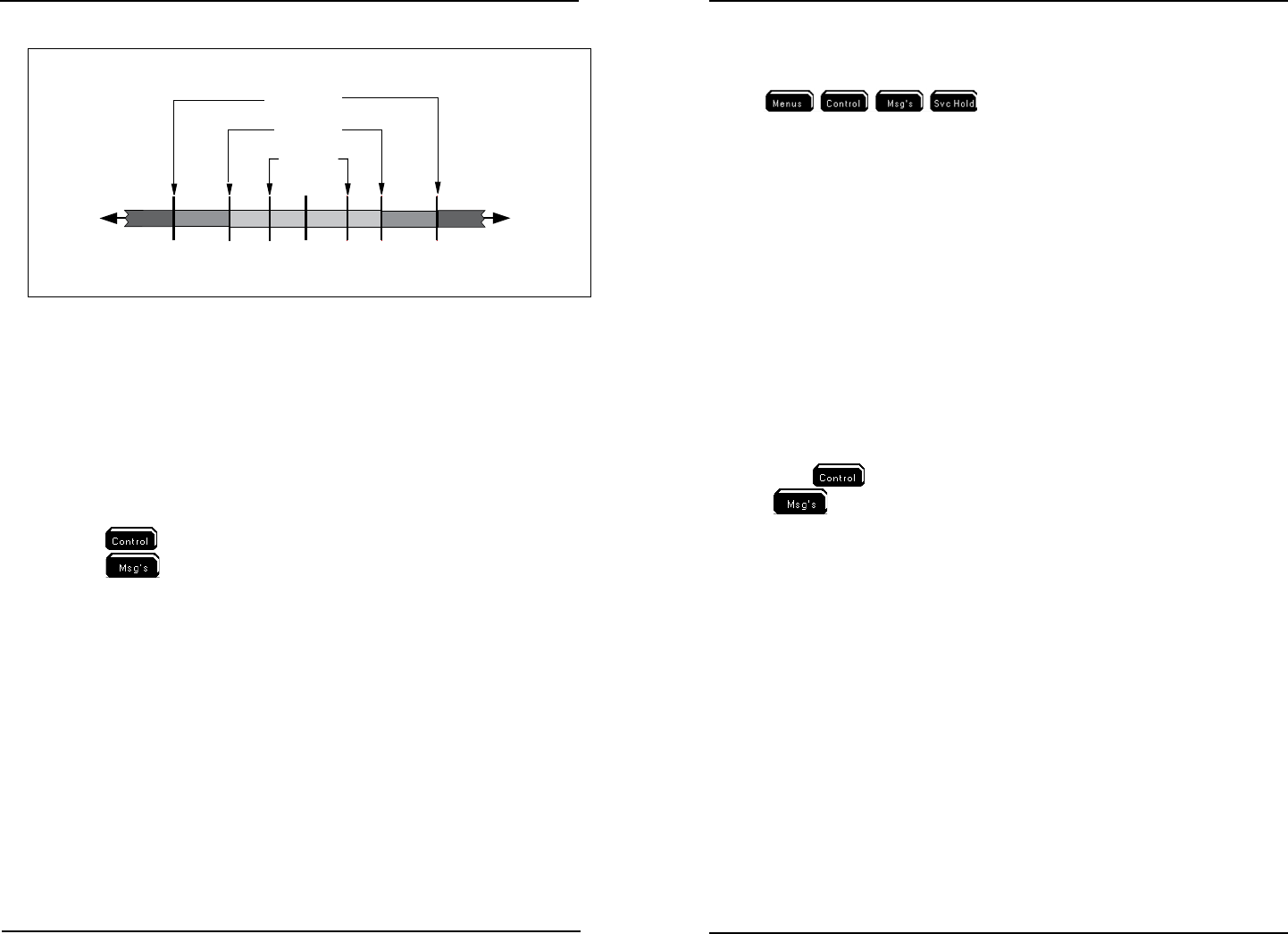
Range #1
Low
Alarm
ON
High
Alarm
ON
High
Range #1
ON
Optimal
S
etpoint
Value
Lower
Parameter
Values
High
Alarm
Setpoint
Low
Alarm
Setpoint
Higher
Parameter
Values
DO Range #2
High
Range #2
ON
Low
Range #1
ON
Low
Range #2
ON
Acceptable
Operating
Range
Temperature have 1 Control Range
DO has 2 Control Ranges
3.5 mg/l 4.0 5.0 8.1 8.5 8.7 8.9
Figure 4.8
Notes:
- Changing control method between PID/PWM and Set Point may result in
invalid setp point, control and alarm value congurations. Always reconrm
sensor setup system menu conguration when control mode is changed.
- DO systems have two control ranges. ey are referred to as Range Low &
Range Low 2 and Range High & Range High 2.
- Control systems remain active when the user is in 5X00 menus.
- Control icons display at the Run Screen when relays are energized - see Icons
- page 78.
- Press
at Run Screen to display active sensor and aux system relays.
- Press
at Run Screen to display events created by control and alarm
relays - see Event Log - page 112.
- Control relays are not energized if the 5X00 DO sensor value reads “Over”
or “Under.”
- “Over” and “Under” are not displayed for aux temperature systems when tem-
perature values are outside the temperature operating range - see temperature
range specication - page 15. Temperature system controls will not operate
correctly when values are outside the temperature operating range.
- See Wire Relays - page 56 for information on wiring control output devices.
Set Point Alarm Values
Alarm values set the acceptable control range. Alarm system(s) do not become
active when values are within acceptable control range. See gure 4.8 - page 140.
Enable and congure system alarm(s) to activate alarm output devices(s), view
alarm icons, hear audible alarm and/or receive alarm notications sent via email or
cell phone (SMS) - page 91. Congure high and low alarm values to set alarm
thresholds. Alarm system(s) becomes active when value is ≤ low alarm value or ≥
high alarm value. Enabled alarm relays energize if alarm condition exists for the
general alarm hold o time. Alarm relays are energized until one of the four so-
keys
is pressed regardless of sensor value. Pressing
one of four sokeys resets the alarm system. Alarm systems become active again
if, aer the alarm hold o period, the alarm condition still exists. Alarm hold o is
congured in the General Alarm menu.
When the General Alarm is enabled, (with or without enabled relay), the general
alarm system becomes active when any system alarm is active. See General Alarm
- page 124.
System low alarm range starts at -1 signicant digit below low control value. High
alarm range starts at +1 signicant digit above high control value.
Notes:
- It is important to keep the 5X00 at the Run Screen during normal opera-
tion. Alarm functionality (email alarms, activation of enabled alarm relays,
alarm icons, and buzzer) is suspended when 5X00 is not at Run Screen.
- Alarm icon(s) display at the Run Screen when alarm condition(s) exists for
longer than the general alarm hold o time. See Icons - page 78.
- Press
at Run Screen to display active sensor and aux system relays.
-
to display events created by control and alarm relays - see Event Log
- page 112.
- Alarm relays are not energized if the 5X00 DO sensor value reads “Over” or
“Under.”
- “Over” and “Under” are not displayed for aux temperature systems when
temperature values are outside the temperature range specication - see tem-
perature range specication - page 15. Temperature system alarms will not
operate correctly when values are outside the temperature range specication.
- See Wire Relays - page 56 for information on wiring alarm output devices.
Validation Error and Autox - Set Point Control Only
When an invalid value is entered at the numeric keypad a Validation Error window
displays. An invalid value is either a value outside the range of the sensor system or
a value that breaches other settings within the sensor system. Autox occurs when
a high or low control value is entered that breaches the set point value. Examples
are provided below:
Low range control value must be < set point value. High range control value must
be > set point value. Low alarm value must be < low control value. High alarm
value must be > high control value.
Conguring the 5X00
Conguring the 5X00