
Manual


YSI 5X00
137
YSI 5X00
136
AquaManager and the System Menu
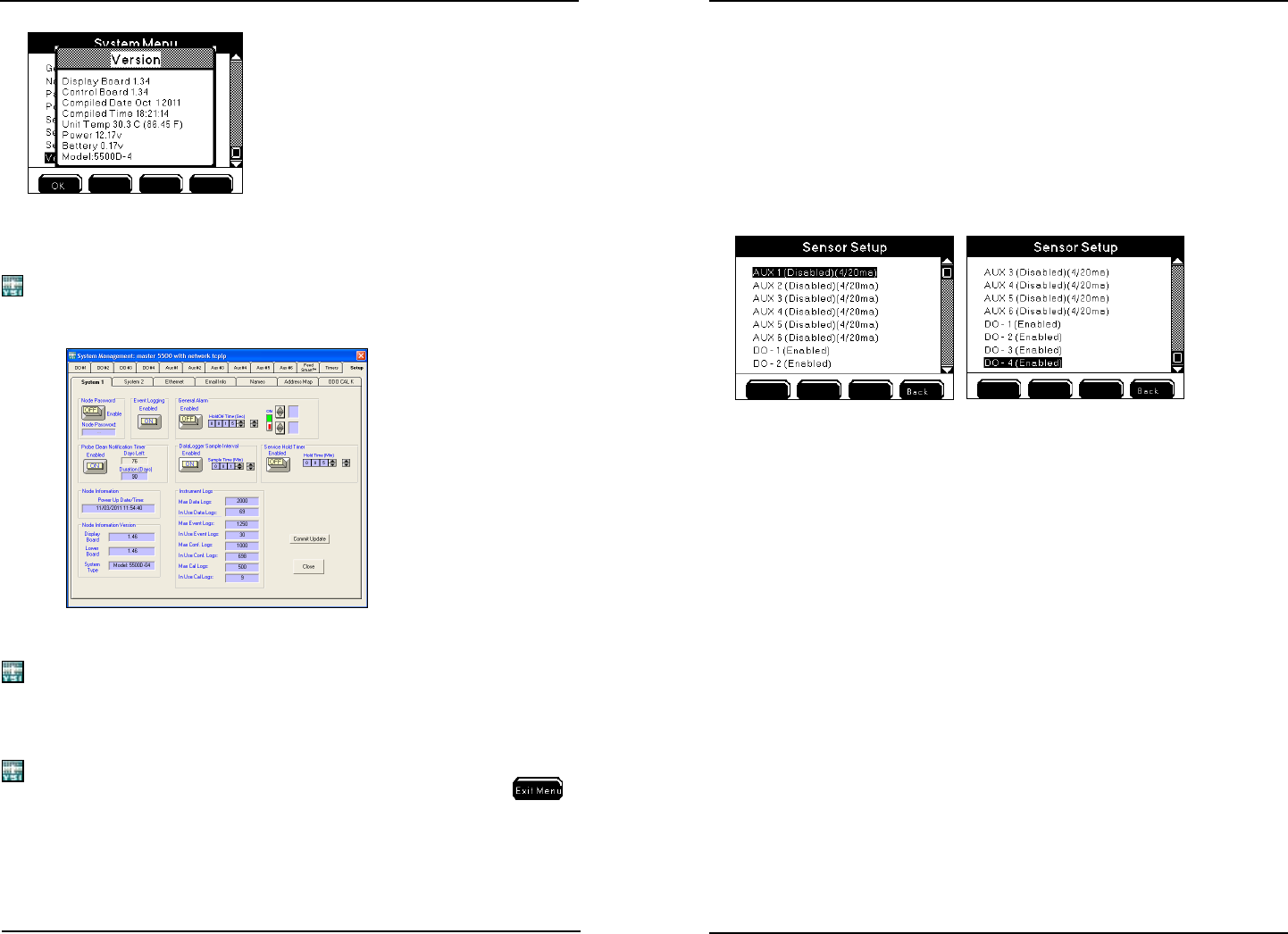
AquaManager users can congure most 5X00 system menus from a PC. Aer polling
the 5X00, use “Systems Management” from the node window to view and upload
5X00 conguration. System menus are congured at the Setup tab selections.
Notes:
- Always manually poll the 5X00 aer uploading conguration changes and
verify uploaded information is retained. When conguration changes are
uploaded using AquaManager at the same time conguration changes are
being made by a user in the menus on a 5X00 instrument, the AquaManager
uploads may not be saved depending on the timing of keystrokes at the 5X00.
- e Run Screen must be displayed during normal operation. If the 5X00
is not at the run screen during AquaManager uploading, pressing
at
the 5X00 will only save certain conguration changes.
-
See Chapter 5 AquaManager - page 175 and AquaManager online help for ad-
ditional information.
Sensor Setup
Menus → Sensor Setup → Aux 1-6
→ DO 1-4
Aux, DO, and temperature system set points, control (set point or PID/PWM),
alarm, and sensor system relays are congured in the Sensor Setup menus. Eight
onboard relays can be congured for control and alarm output devices. Enabled
relays energize when a control or alarm system is active. Alarm notications can be
sent via email or cell phone (SMS messaging) - page 91.
Notes:
- For normal operation, the 5X00 must be at the Run Screen. Alarm func-
tionality (email alarms, activation of assigned alarm relays, alarm icons,
and buzzer) is suspended when 5X00 is not at Run Screen.
- Sensor system must be enabled in order to display values at Run Screen.
Control and/or alarm relays will not energize regardless of value if the
sensor system is disabled.
- ere is a 30 second delay at power up before control, timer, and alarm systems
become active.
- ere is a 30 second sensor system hold o when sensor conguration is
changed. See 30 Second Sensor System Hold O - page 146.
- Calibrate sensor prior to use. See Calibration - page 83.
- “Over” and “Under” readings are displayed when DO sensor is measuring
outside it’s operating range - see DO range specification - page 14 DO
control and alarm functions including relays are suspended when a sensor is
reading “Over” or “Under.”
- “Over” and “Under” are not displayed for aux temperature systems when tem-
perature values are outside the temperature operating range - see Temperature
Range Specication - page 15. Temperature system controls and alarms will not
operate correctly when values are outside the temperature operating range.
- DO “Over” and “Under” readings most likely indicate that the sensor needs
to be serviced or replaced, or a bad probe or cable connection exists.
Conguring the 5X00
Conguring the 5X00