
Manual


YSI 5X00
135
YSI 5X00
134
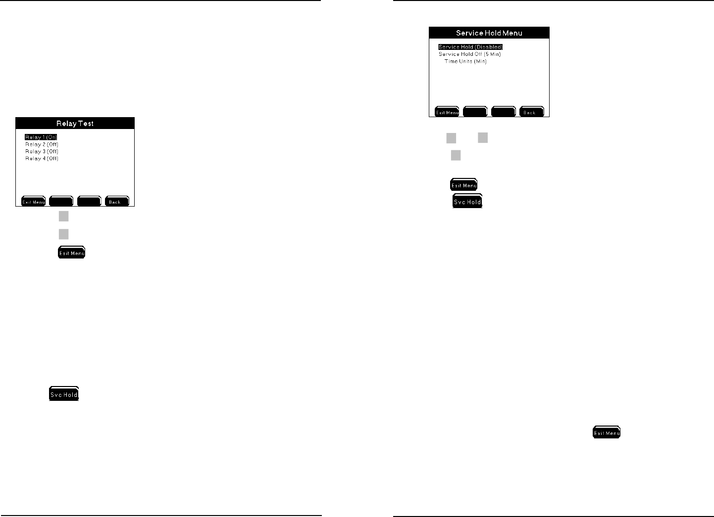
Relay Test
Menus → System → Service→ Relay Test
Use the Relay Test menu to verify peripheral devices are wired correctly. Entering
this menu turns o any active relays and disables any sensor, aux, and timer system
relays from energizing regardless of value or condition. Systems are not reset when
the Relay Test menu is exited. Reset systems aer exiting the Relay Test menu,
cycling power to the 5X00.
1. Press
to toggle relay on.
2.
Press
to toggle relay o.
3. Press
to save conguration and return to Run Screen.
Note:
- Timer and control icon(s) remain at the Run Screen until the system is reset.
Example - the timer icon remains at systemwide location until the end of
the timer cycle that was stopped when the relay test menu was entered even
though the relay is not energized. To reset systems aer exiting the Relay Test
menu, power cycle the 5X00.
Service Hold
Menus → System → Service Hold
Pressing
at the Run Screen puts the 5X00 into Service Hold. e Service
Hold time is user selectable (1-255 sec, min, or hours). Service Hold turns o any
active relays and disables any sensor, aux, and timer system relays from energizing
regardless of value or condition. 5X00 alarm emails are not sent during service hold.
Aer the service hold time expires or is cancelled, the sensor systems are reset aer
30 seconds. Timer systems are not reset. See Service Hold Menu - page 173 for
additional information.
Conguring the 5X00
1. Use
▲
and
▼
to scroll and highlight submenus.
2.
Press
to select.
3. Enable and congure submenus.
4. Press
to save conguration and return to Run Screen.
5. Press
at Run Screen to enter Service Hold . See Svr Hold page
173 for additional information.
Note:
- Place the 5X00 in service hold as instructed in step 3 of calibration checks in
Maintenance, page 189.
Version
Menus → System →Version
e Version menu contains information about the 5X00 including: display and
control board rmware code version, rmware compile date and time, control board
temperature, AC and DC voltage and model number.
Notes:
- Firmware version information is required when contacting YSI support.
- e clock chip temperature range starts at 0C. Values < 0C are not valid
numbers.
- e normal operating range temperature will be a few degrees above ambient.
- AC powered units will run at a higher temperature than DC powered units.
- To view current AC and DC power values
to return to run screen
and then return to menu. Power information does not refresh when version
menu is open.
Conguring the 5X00