
Manual


YSI 5X00
99
YSI 5X00
98
potentially delay any AquaManager alarm emails from being sent.
- To disable the serial to ethernet device from sending alarms, clear all four
email addresses from the Communication → Ethernet menus. Clear the email
addresses by using the “Spc” (space) key on the numeric keypad. Save change
at numeric keypad and press
to save conguration and return to Run
Screen.
Ethernet Module Error Message
At power up, the serial to ethernet device will generate an error message if it cannot
properly handshake with the 5X00 hardware. If this error occurs, communication
(AquaManager and 5X00 alarm emails) will not work via TCP/IP. e error could
be a result of incorrect serial to ethernet device installation or a faulty ethernet
device. e error message will appear in the event log.
SMS Messaging with Ethernet Module
SMS (Short Message Service) or text messaging is a service for sending messages to
your cell phone or mobile device. To use SMS messaging, enter the email address
in the Menus → System → Communications→ Ethernet →Email address. See Ap-
pendix 6 SMS - page 235 for a list of cellular and mobile companies that support
sending text messages.
Node Network
Menus → System → Communications → Network
A node network refers to either one stand alone master node and/or one master
node and up to 31 congured and wired slave nodes. Node networks with at least
one slave are physically connected using RS485 protocol see page 62 for additional
information. Only the master node is congured for serial or ethernet module
communication.
On a network with at least one slave the master continuously queries enabled slaves
on the network. e master is the access point for the entire network. is includes
Conguring the 5X00
AquaManager communication and sending of 5200A/5X00 alarm emails. Slave
nodes must be congured with a slave address.
Note:
- Multiple node networks communicating via direct connect (RS232) require
separate PC COM ports for simultaneous AquaManager mapping and auto-
polling.
1. Wire 5X00 network - page 62.
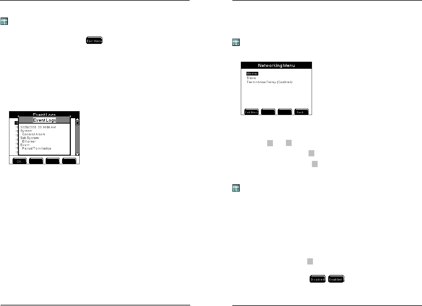
2. Enter Network menu
Menus → System → Communications → Network
3.
Press
▲
and
▼
to scroll and highlight submenus.
4. For master node: Press
at master submenu.
5. For all slave nodes: Press
at slave submenu. Congure a slave ad-
dress.
Note:
- e slave address appears as the slave subnode at node properties.
- Congure slave addresses with numbers of 1 through 31. Slave addresses of
32 to 64 will be used in future releases and should not be congured with the
current release.
6. Disable the Termination Relay on all devices except the rst and last
device on the network. Menus → System → Communications → Network
→ Termination Relay.
7. Verify that the Termination Relay is enabled on the rst and last device
on the network.
8. For master node: Press
at master submenu. At assign slaves menu,
select the slave address congured in step 5 above. Press enter. Enable
one slave at a time using
sokeys.
Conguring the 5X00