
Manual


YSI 5X00
61
YSI 5X00
60
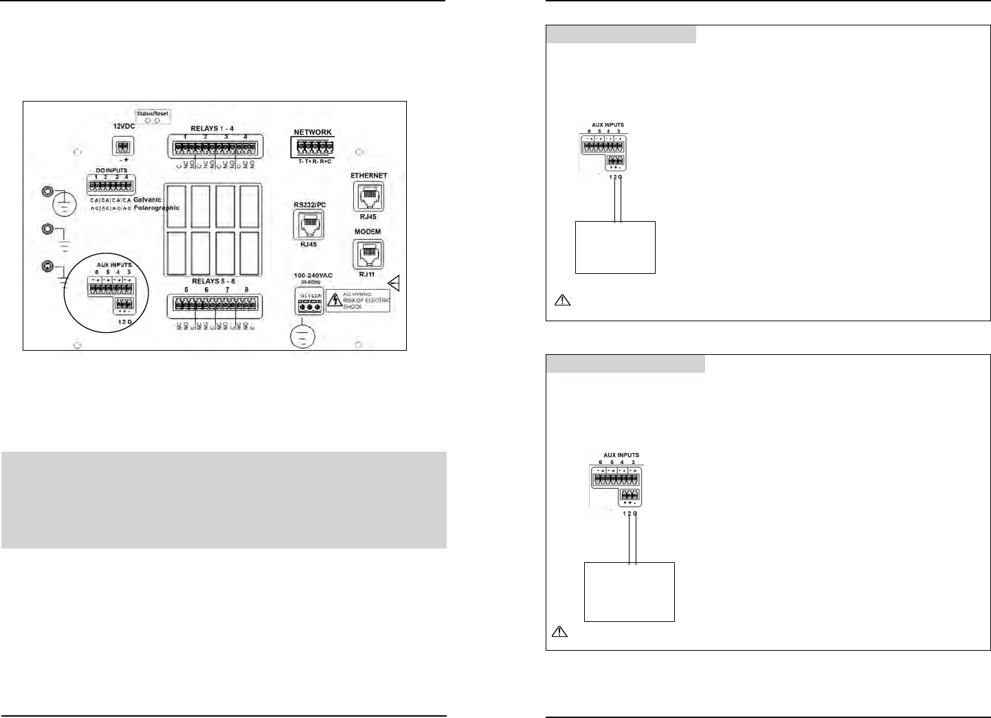
See Digital Input example - gure 3.24 and Analog Input example - gure 3.25.
CAUTION: e auxiliary inputs are not isolated. Devices connected must be
electrically isolated from ground and the water.
Do not connect or disconnect IDC ribbon cable
when 5400 is powered. Serious damage can occur.
Figure 3.23
5. Complete other wiring to 5X00.
6. Close front panel - page 43.
7. Test aux systems.
Test Auxiliary Input Devices
Apply power to 5X00. See Aux Setup - digital page 148 and analog (non tempera-
ture) page 150 for conguration information. Verify display, control, and/or alarm
functionality based on user dened conguration.
Wire Aux Digital Input
1. Install aux digital device according to manufacturer’s instructions.
2. Connect switch wires to Aux Input 1 - 6. Connect ground wire to (G) at
location M
for aux 1 and 2 or to (-) at L
for aux 3, 4, 5, or 6. Connect the
other wire to (+) L
and to 1 or 2 at M
.
Instrument with
analog voltage
output
Auxiliary Input Connector
+ -
CAUTION: Do not input external voltage.
Figure 3.24
Wire Aux Analog Input
1. Install analog instrument according to manufacturer’s instructions.
2. Connect analog instrument wires to Aux Input 1 - 6. Connect ground wire to
the (G) at M for aux 1 and 2 or to (-) at L for aux 3, 4, 5, or 6. Connect the
other wire to 1 or 2 at M for aux 1 and 2 or to (+) at L for aux 3, 4, 5, or 6.
Instrument with
analog voltage
output
Auxiliary Input Connector
+ -
CAUTION: Observe correct polarity on analog input.
Figure 3.25
Installation and Wiring
Installation and Wiring