
Manual


YSI 5X00
55
YSI 5X00
54
5. Wire temperature sensors. Temperature sensors are wired as auxiliary inputs.
See Temperature Sensor(s) - page 54.
6. Complete other wiring to congure 5X00 system.
7. Close Front panel -page 40.
8. Calibrate DO sensor - see Calibration “DO” on page 85.
CAUTION: Do not ground the probe body.
Test DO/Temperature Sensors
Apply power to 5X00. See DO Sensor Setup - page 154 to congure DO sensor
inputs. See Temperature Setup - page 150. Calibrate the DO sensor, see DO
calibration - page 82. Verify changes in sensor values occur when the sensor is
placed in environments of dierent oxygen concentration and temperature. For
example, the DO reading in saturated air for calibration versus the DO reading
when the sensor is placed in a zero oxygen environment (mix 1 gram sodium sulte
in 0.5 liter of water).
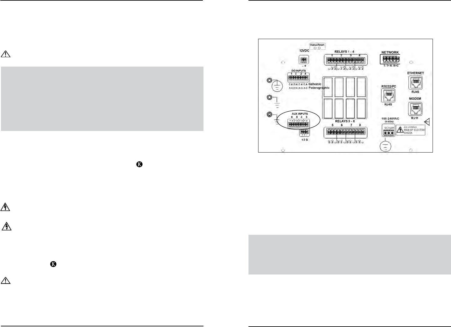
Wire Temperature Sensor(s)
e 5X00 system will support four Temperature/Aux Analog inputs. Temperature
sensors have 2 wires and are terminated at location (5500) L (5400) on I/O
Board - figure 3.20. Temperature sensor(s) must be thermistors with 10K at 25C,
see Appendix 6 Alpha A Curve - page 236.
Directions to Wire Temperature Sensor(s)
WARNING: Disconnect external power to the unit before wiring.
AVERTISSEMENT: déconnectez l’alimentation externe de l’unité avant d’eectuer
un câblage quelconque.
1. Mount and install 5X00 and probes - page 27 and page 33.
2. Open front panel - page 42.
3. Feed temperature probe cable through drilled hole in rubber grommet
to location
(5500) L (5400). e terminal strip is removable.
CAUTION: Run high and low voltage cables through separate bulkhead and
conduit.
4. Terminate temperature sensor wires to Aux 3, Aux 4, Aux 5, and/or Aux
6 system. ere is no polarity for temperature sensor wires; therefore,
(+) and (-) terminals are interchangeable. Make sure the temperature
sensor wires are terminated to the (+) and (-) terminals for the Aux
system (3, 4, 5, 6) you are conguring.
Do not connect or disconnect IDC ribbon cable
when 5400 is powered. Serious damage can occur.
Figure 3.20
5. Complete other wiring to congure 5X00 system.
6. Close front panel - page 43
7. Test temperature sensor.
Note:
- Temperature sensors wired to Aux 3, Aux 4, Aux 5, and Aux 6 are displayed
on the 5X00 by default as Temp 1, Temp 2, Temp 3, and Temp 4 respectively.
For instructions on changing the default display settings, see section Name
Devices/Sensors in Chapter 4 Conguring the 5X00.
Test Temperature Sensor
Apply power to 5X00. See Temperature Set up- page 150 to congure temperature
system. Place the temperature sensor in solutions of varying temperature and verify
the sensor readings with another temperature sensor.
Installation and WiringInstallation and Wiring