
Manual


YSI 5X00
53
YSI 5X00
52
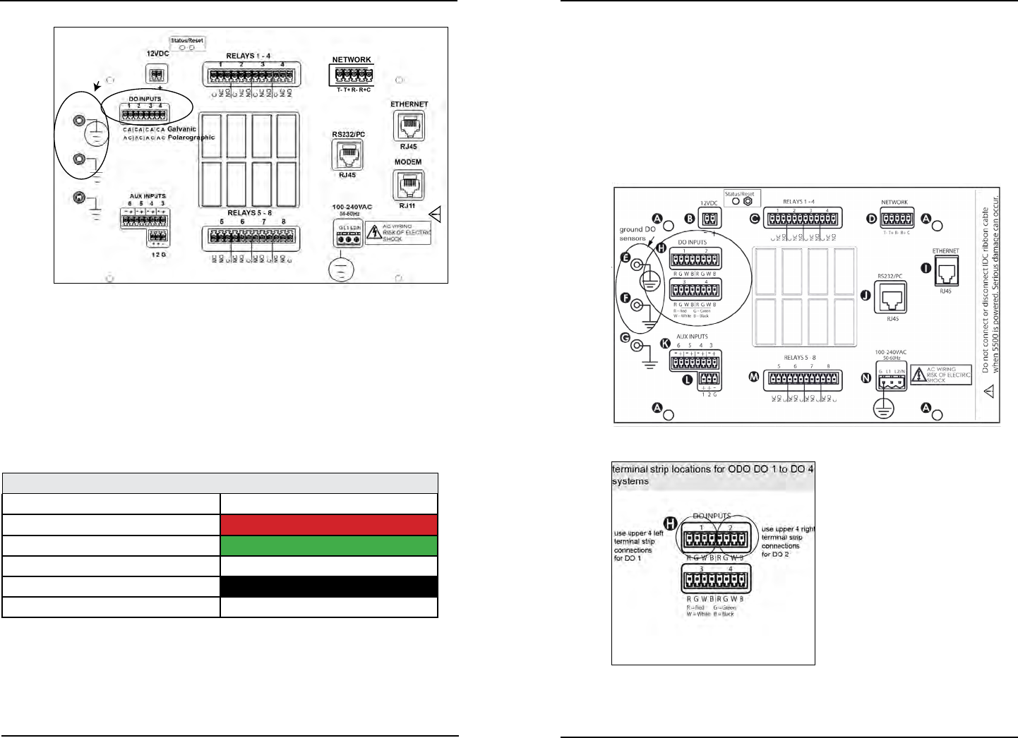
Do not connect or disconnect IDC ribbon cable
when 5400 is powered. Serious damage can occur.
ground DO
sensors
Figure 3.19
Proceed to Step 5 following 5500 DO sensor wiring directions page 52 to complete
sensor wiring.
4. On 5500D instruments there are two terminal strips at location H. Wire
system DO-1 and system DO-2 sensors to the upper terminal strip. Wire
system DO-3 and system DO-4 sensors to the lower terminal strip - see
gures 3.19a and 3.19b. e upper and lower DO sensor terminal strips are
inverted. Be sure ODO sensor wires follow the wire coding below.
YSI 6060250 ODO/temperature digital sensor cable YSI
Wire Function Color Coding
power/6.3 volts DC for ODO Probe RED
GND/Sensor GREEN
RS485 B/bidirectional data WHITE
RS485 A/bidirectional data
BLACK
Ground/drain wire BARE
• YSI 6060250 ODO DO sensor wires are red, green, white and black.
-Terminate red wire to 1R (“1”=DO1 “R”=red) and/or 2R, 3R, 4R.
-Terminate green wire to 1G (“1”=DO1 “G”=green) and/or 2G, 3G,
4G.
-Terminate white wire to 1W (“1”=DO1 “W”=white) and/or 2W,
3W, 4W.
5500
-Terminate black wire to 1B (“1”=DO1 “B”=black) and/or 2B,
3B, 4B.
-Terminate bare ground/drain wire to E or F on metal plate.
Notes ground/drain wire termination:
- Install a ring (eyelet) or spade (fork) terminal onto the ground bare wire before
terminating ground wire to E or F.
- Multiple ODO ground/drain wires can be terminated to the same ground
location on the metal plate.
- Return screw at E or F over terminal connection of ground wire.
Figure 3.19a
Figure 3.19b
Installation and WiringInstallation and Wiring