
Manual


YSI 5X00
49
YSI 5X00
48
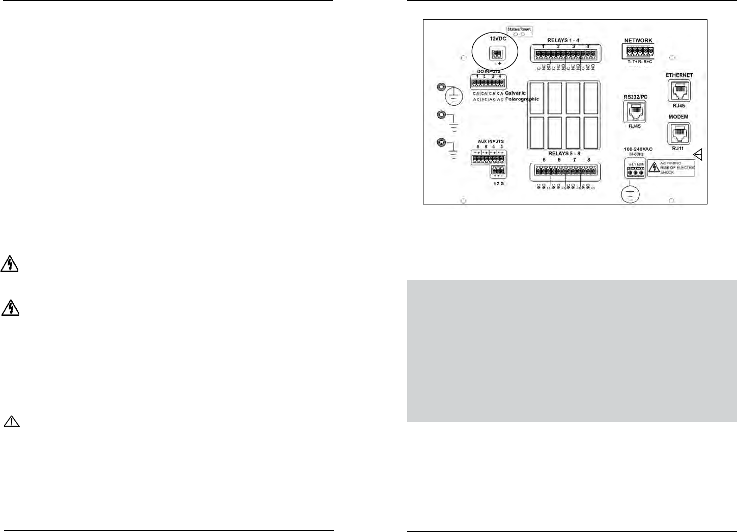
Wire DC Power and Backup Power
e 5X00 may be powered by most regulated 9.0-16.5 VDC source that provides
800mA of current and is isolated from mains supply by double or reinforced insula-
tion. e DC power source is user supplied and could be lead acid, gel cell, or UPS
(with 12VDC transformer) external batteries. DC power wires are terminated at
location B on the I/O Board - Figure 3.18 (Common lettering references are used
for both 5400 and 5500 models).
Notes:
- e 5X00 does not charge batteries. Quality assurance maintenance proce-
dures should be established if batteries are to be fully powered when used as
back-up power source.
- Power supply voltage above 16.5 VDC may permanently damage the 5X00.
- When back up voltage falls below 9.0 volts, the 5X00 ceases to operate properly.
- Some switching DC power supplies not supplied by YSI may result in noisy
readings.
Directions to Wire DC Power/DC Backup Power
WARNING: Disconnect external power to the unit before wiring. Follow all manu-
facturer’s safety and installation instructions when providing power to the 5X00
via a DC power supply.
AVERTISSEMENT: déconnectez l’alimentation externe de l’unité avant
d’eectuer le câblage. Suivez toutes les consignes de sécurité et d’installation du
fabricant lorsque vous fournissez de l’alimentation au modèle 5X00 par un bloc
d’alimentation à courant continu.
1. Perform steps 1-3 of 5X00 installation.
2. Open front panel - page 42.
3. Feed DC power cable through drilled hole in rubber grommet to location
B. Terminal strip is removable.
CAUTION: Run high and low voltage cables through separate bulkhead and
conduit.
4. Terminate DC power wires to pins (-) and (+) according to manufacturer
instructions and any applicable local electrical codes.
Do not connect or disconnect IDC ribbon cable
when 5400 is powered. Serious damage can occur.
Figure 3.18
5. Complete other wiring to 5X00.
6. Close front panel - page 43.
7. Test DC power.
Test DC Power
Connect DC power cable to power source. e enabled system values will display
on Run Screen aer initial YSI splash screen. Verify DC power at the Menus →
System →Version menu - page 135.
See Power Fail Menu - page 128 for DC low battery trigger monitor and alarm
information.
Note:
- e 5X00 will not power up if DC power supply wires are terminated incor-
rectly.
Installation and Wiring
Installation and Wiring