
Manual


YSI 5X00
39
YSI 5X00
38
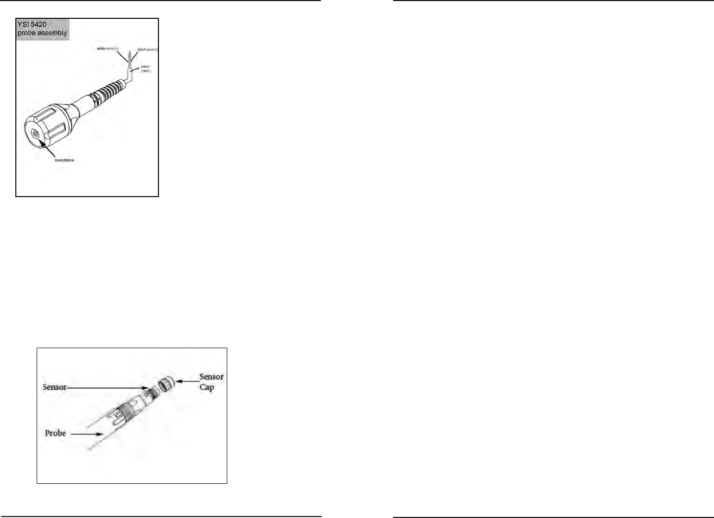
Figure 3.12
YSI 626250 ODO (Optical Dissolved Oxygen) sensor
e YSI 626250 probe assembly includes an ODO sensor and sensor cap. Sensor
cap refers to the removable sensing cap that is replaced about once per year (Figure
3.12a) YSI 626250 probe assembly includes a temperature sensor. An instruction
sheet is included with replacement sensor caps. is instruction sheet is important
because it includes the calibration coecients for your sensor cap. Aer using this
sheet for general probe setup, be sure to store it in a safe place in case you need to
reload these calibration coecients in the unlikely event that they are ever deleted
from the probe.
Figure 3.12a
5500
Directions to prepare the ODO probe for the rst time:
1. Remove the metal probe guard from the probe by turning it counterclock-
wise.
2. Remove the red storage cap which contains a moist sponge from the end of
the probe by pulling it straight o the sensor. Save this to use later for long
term storage.
3. Reinstall the probe guard by sliding it carefully over the sensor and then
threading it onto the cable/probe assembly with a clock.
4. Calibrate probe - page 85.
Notes:
- A new cable/probe assembly already has a sensor cap installed and the sensor
cap coecients are preloaded into the probe at the factory.
- Perform ODO calibration whenever ODO caps are replaced see Calibration
page 85.
Install Temperature Sensors
e 5X00 system will support 4 Temperature/Aux Analog inputs. Temperature sen-
sors are included on YSI 5421 (galvanic), 5422 (polarographc) and 626250 sensor
and/or sensor assemblies. Alternate temperature sensors can be used but must be
thermistors with 10K at 25C . See Appendix 6 Alpha Curve - page 236.
Aer installing the temperature sensor in its monitoring location, see Wire Tem-
perature Sensors - page 54.
Probes should be serviced on a regular basis. See Probe Maintenance - page 191.
Wiring Information
System components must be wired correctly to ensure reliable performance and
accurate data collection. Directions are provided on the following pages for wiring
all components and peripheral devices.
PCBs
ere are four printed circuit boards (PCBs) inside the 5X00 enclosure. ey are:
- Display board (mounted in the front panel)
- I/O board is attached to a metal plate inside the enclosure and is visible when
front panel is removed
- DO daughter board mounted to the I/O Board
- Control board (connected to the under side of the I/O Board)
Installation and Wiring
Installation and Wiring